Adjustable voltage box mod

Status
Not open for further replies.

misterD

Ultra Member
ECF Veteran
Verified Member
Dec 27, 2009
2,632
653
worster - crappychusetts
thanks BB. i got that about not going to low and i think with a 200K it wouldn't happen. i have a sliding switch that disables the booster so i can vape low voltage from the single batt. my problem is that the variable isn't working. i have to see if the reason of that is becos i have the ground hooked somewhere else in the box instead of having it right at the booster. its the only thing i can think of...
turns out the Adj must been effed up. i got rid of the resistor between Adj and Vout and the output remained unchanged. there i go ruining my 3rd boobster. :(
 
Last edited:

bigblue30

Super Member
ECF Veteran
thanks BB. i got that about not going to low and i think with a 200K it wouldn't happen

If you have it wired like the picture in my last post,but without the fixed resistor you should be able to go from 200k to 0 ohms.

Adj must been effed up. i got rid of the resistor between Adj and Vout and the output remained unchanged. there i go ruining my 3rd boobster. :(

By unchanged do you mean it stays a 0 volts?
 

misterD

Ultra Member
ECF Veteran
Verified Member
Dec 27, 2009
2,632
653
worster - crappychusetts
By unchanged do you mean it stays a 0 volts?
it was putting out 4.6V unloaded and 4.3 under load. i had a resistor running between Vout and Adj that was supposed to bring the V even lower so i took it out and was still getting 4.6V and 4.3V. im using a new boobster now and all is fine. i tested everything b4 soldering. its waiting on the POT though. but im still not sure if the wiper goes into Adj and the other pin to ground. and Nuck suggested to use an extra resistor on that pin to make sure the voltage wouldnt go to high...
 

bigblue30

Super Member
ECF Veteran
it was putting out 4.6V unloaded and 4.3 under load. i had a resistor running between Vout and Adj that was supposed to bring the V even lower so i took it out and was still getting 4.6V and 4.3V. im using a new boobster now and all is fine. i tested everything b4 soldering. its waiting on the POT though. but im still not sure if the wiper goes into Adj and the other pin to ground. and Nuck suggested to use an extra resistor on that pin to make sure the voltage wouldnt go to high...

I connect the wiper (middle pin) to the adjust pin (pin3 on the booster). Then I connect 1 of the other 2 to ground. It does not make a difference what one you connect to ground.

When you do this you will have a resistor that goes from 200k to 0.

If you look at the picture in my post #40...one page back. you will see the extra (fixed) resistor I told you about.
 

bigblue30

Super Member
ECF Veteran
can i ground it anywhere in the box? cos i dont wanna mess with the boobster. i fried 2 of em already!
mang! if i was Santa id bring you an early nice soldering station with a whole bunch of girls to dance while you play with modding!!! :D

Ground is ground..If you are using Nuck's circuit....you can connect it any where on the ground line...like at the minus side of the atty, the drain side of the Mosfet, or even splice into the wire that is going to the booster pin 1.

Would it help if I use my bread board and wire one, and take a picture of it. That way you could see how it look wired up out in the open.
 

misterD

Ultra Member
ECF Veteran
Verified Member
Dec 27, 2009
2,632
653
worster - crappychusetts
i think im fine, BB! my problem now is that i dont have a 36K resistor.
i have 10k, 47k, 75k, 100k and 150k. how can i get close to 36k?
Shortstuff gave me this link and im trying to find the right combo.
Resistance - DiracDelta Science & Engineering Encyclopedia
hey!:D i can tight 2 of the 75!!!
 

bigblue30

Super Member
ECF Veteran

WillyB

Vaping Master
ECF Veteran
Oct 21, 2009
3,709
591
USA
i think im fine, BB! my problem now is that i dont have a 36K resistor.
i have 10k, 47k, 75k, 100k and 150k. how can i get close to 36k?...
Where do need the 36K resistor?

In general using the board naked should provide 5V. Adding a diode at the atty should bring that voltage down to about 4.3 (more or less). Not all diodes (sample to sample or types) are identical. Test a few first. The 3A RS barrel diodes according to Ralph T dropped his mod .8V.

So basically with your added switch and only a diode you have voltages of 3.8 (one batt), and 4.3.


Take a look at Mamu's excellent diagram

5V_mamu_veroboardcircuit_small.jpg


This may be an odd way to achieve her voltage, but she (an experienced vaper/modder) says it's her sweet spot.

According to the spec sheet the 43k resistor should provide about 5.7V, adding the diode drops that about .7V (different diodes may provide different results).

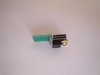
This is what a variable resistor (trimpot) looks like.

variable_resistor.gif

You would use 'W' (wiper) and either 'A' or 'B'. The difference is the rotation, the end effect on voltage is the same.

Again according to the spec sheet a 25kΩ resistor should result in about 6.1V. Adding the diode into the mix would bring you down to a max voltage of about 5.3V or so.

So using one of these:

https://www.jameco.com/webapp/wcs/stores/servlet/Product_10001_10001_254692_-1

In place of Mamu's 43K resistor should now give voltages of 3.8 and 4.3 variable to 5.3V max.

These are all theoretical, an actual circuit may need slightly different values and produce slightly different voltages.

One diode, one trimpot... done.

I hope I got it right. :unsure:
 
Last edited:

bigblue30

Super Member
ECF Veteran
MisterD,

We probably should have started another thread to talk about the booster, but as long as it’s already here in this post, let me see if I can answer some of the questions.

I believe you wanted to build a “fistpack” type mod, and you wanted to replace the slider switch and the 3 resistors (47k, 72k, and 147k) with a POT, because you said this:

“MisterD
its gonna be a fistpack JB with a POT instead of a sliding switch and fixed resisters!”


You then asked if you could use the 200k pot that I was using in my mod.

“how do i wire this POT? it has 3 pins (1, 2, 3) i presume that 2 is ground and then i wire one of the others to Adj.”

If you look at the circuit that WillyB provided…You replace the 47K with pin 1 and 2 of the POT.


5V_mamu_veroboardcircuit_small.jpg


BUT, the problem with the POT is……It can be adjusted from 200k to 0 (zero) ohms.

WillyB cautioned us about using a POT when he said:
”It would also appear that you do not want your Vout to be less than 4V as this may damage the booster. So some care will be needed with a pot
I think WillyB was warning us not to put the POT across the Vout and adjust pins, because no amount of resistance across the adj pin will make the booster output less then 4 volts.

The FistPack instructions say you can put a 100k across the Vout and Adj to lower the output to 4 volts, and since the POT can be adjusted to 0 ohms….that could be a problem.

So as long as we are clear that the POT is going from Adj to ground….We still have the problem of the POT being able to be adjusted to 0 ohms and causing a “short” to the adj pin of the booster.

I told you to put a “fixed” resistor from the center pin of the POT to the Adj pin of the booster…..This guarantees that even if you adjust the POT to 0 ohms you will never be able to go lower the “fixed” resistor value.

You came up with a value of 36k for that fixed resistor value.


WillyB then asked

“Where do need the 36K resistor?”
You need the 36K “fixed” in line with pin 2 of the POT to make sure that the POT does not get adjusted too low.

WillyB suggested using the 25K POT below:


I believe you need to decide, what is the “lowest” value of resistance that you want to put across the adjust pin and use that value as the fixed resistor in line with the POT..
 

bigblue30

Super Member
ECF Veteran
Nice guide, I have a question about the pot you're using. Is there any disadvantage to using a single turn 200k pot vs a multi turn similar to the one you're using?

More specifically this one https://www.jameco.com/webapp/wcs/stores/servlet/ProductDisplay?productId=182844

That will work find...electrically. With the 25 turn POT each turn is about .2 volts. It takes 10 turns to adjust from 4 to 6 volts.

With the 240 degree POT 9 degrees of movement is .2 volts and 90 degrees are 2 full volts. It works but it is a little harder to “dial” it in.

I have thought about adding a thumb wheel (1/2 inch diameter) to the adjustment pin. About a ¼ turn would take you from 4 to 6 volts.


mamu

Ultra Member
ECF Veteran
Verified Member
Mar 29, 2009
2,551
1,523
IN USA
...This may be an odd way to achieve her voltage, but she (an experienced vaper/modder) says it's her sweet spot.

Why thank you Willy for the kind words. I think it gives me just a bit more umph than the naked 5v output. I don't think the diode I use drops it a full 0.7v.

It's been my sweet spot for a while, but lately I find I want a bit more during evening hours. I don't know, maybe tolerance has set in and I need more of a hit during certain times.

So I've been experimenting with the TI booster with lower resistors (36K ohm) and the prob is you really can't get much more than that 5 volts (5.1 volts is tops) from the booster without getting the whine from it and it shutting down. I'm using a 510 atty which is exceeding that 12 watt limit of the booster thus the whining sound and it shutting itself off. I've been searching for a DC-DC converter that doesn't have that 12 watt limit and with similar specs to the TI booster but no luck so far. It's great to use 1 18650 3.7v batt with high mAh, but I think I've come across a dead end for that and the 2 18650 batts makes for a pretty good sized mod, so I'm trying to go for a smaller enclosure.

@bigblue30: I'd like to experiment with your idea here with the POT. I pretty much get how you've done it, but for the heat sink. Can you provide a part number?? :)

Also, I don't see much of a difference between the UCC383T-ADJ and the UCC283T-ADJ. Is one preferred over the other? I'm also looking at this LDO: KA278RA05C. It's 2 AMP rather than 3 AMP and it's recommended to use a heat sink to get to 15 watts. Also, did you use a gel with the heat sink?
 
Last edited:

bigblue30

Super Member
ECF Veteran
[
@bigblue30: I'd like to experiment with your idea here with the POT. I pretty much get how you've done it, but for the heat sink. Can you provide a link to specs on the heat sink, the part number, and how it's configured alongside the LDO?? :)

The Heat sink is a heat sink off of a RC car speed controller. I have about 10 of them that are 10 years old. I just cut one into 10 pieces and drilled a hole in it to mount it.

It looks like the metal piece on top of this speed controller before I cut it up:
Novak Rooster Crawler Brushed ESC Speed Control - 1841 - eHobbies

Also, I don't see much of a difference between the UCC383T-ADJ and the UCC283T-ADJ other than the temperature range. Is one preferred over the other?

I have used both and I find that they are the same. I have not found any difference in them.


I'm also looking at this LDO: KA278RA05C. It's 2 AMP rather than 3 AMP and it's recommended to use a heat sink to get to 15 watts

I have not used that chip. I just looked at it and found a price of $.70....not bad.
 

mamu

Ultra Member
ECF Veteran
Verified Member
Mar 29, 2009
2,551
1,523
IN USA
hmmm... don't think I'd be buying that particular heat sink then. That's innovative to find something lying about to use though.

With your inspiration in mind I think I'll look through our old computer parts. Might find an old motherboard that has a heat sink or something useful along those lines.

Thanks and thanks so much for sharing!!

Edit: I wanted to ask about what size did you cut your heat sink??
 
Last edited:

bigblue30

Super Member
ECF Veteran
hmmm... don't think I'd be buying that particular heat sink then. That's innovative to find something lying about to use though.

With your inspiration in mind I think I'll look through our old computer parts. Might find an old motherboard that has a heat sink or something useful along those lines.

Thanks and thanks so much for sharing!!

Edit: I wanted to ask about what size did you cut your heat sink??

Below is what it looks like. It is the same size as the chip (10mmX12mmX5mm). You can increase the cooling efficiency by add a layer of heat sink compound between the Amp and the heat sink:
Heat Sink Grease (6g) - RadioShack.com

Looking for the compound I found this one a RS. It is made for the TO-220/TO-202 chip:
TO-220/TO-202 Aluminum Heat Sink - RadioShack.com
 

Attachments

  • DSC03159.jpg
    DSC03159.jpg
    13.9 KB · Views: 169
Status
Not open for further replies.

Users who are viewing this thread