Here is a parts list from Mouser.com if anybody is looking for the parts.
Note the 470k resistor I ordered is a surface mount (SMD) NOT a through hole.
Dan
Scubabatdan,
Is your 4th line item a 200 ohm pot? It should be a 200k.
Last edited:
Here is a parts list from Mouser.com if anybody is looking for the parts.
Note the 470k resistor I ordered is a surface mount (SMD) NOT a through hole.
Dan
That does look good.
Scubabatdan,
Is your 4th line item a 200 ohm pot? It should be a 200k.
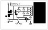
Yes, and Yes I have tried a touch switch but I needed a 100M resistor to make it more sensitive for dry skin as Ceasar suggested. I do find them more reliable in the long run. Here is my schematics for the PCB, all the resistors will be surface mounted not through hole ones.
Who needs a stinkin beadboard
Dan

Dan,
If you left the lands wider (leave more copper) do you think it would help to heat sink the regulator better?
How about increasing the lands, and leaving a copper area larger than the chip to disapate the heat. Could use CPU paste to help the transfer of heat from the chip to the copper area like this:
Dan
")
Anything to cool these chips down would be great. As long as you can still fit it in the mod...lol.
Oh, he has got a Turbo Fan in the works too..
I got some cooling kit for my computer years ago and got a bunch of little heat sinks like these Zalman ZM-RHS1 VGA RAM Heat Sinks - FrozenCPU.com
I'm wishing I still had those now.
Remember that the less copper you remove from the board, the better it will etch. As soon as you require etching larger areas, the thinner areas will not etch as clean.
The added benefit is heat transfer and higher current carrying capacity.
Well since they use copper shims on CPU's I naturally thought a larg copper area you could bolt the LDO to would help dissapate the heat.
YES! and I have not found a spot yet in the PCB to put it since I have to run at 3vdc, I will have to cap the voltage to 3v.
Me too! I still have alot of computer parts will have to revisit that box
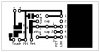
Agreed I will make the trace leads fatter so I have less to etch, but even when I did the small chip above, it worked very well with .010 trace leads. I have reworked the entire layout since I went back to make sure I had the proper spacing for the chips and found the LDO needed to be flipped around to take advantage of the copper heat sink. I have layed it out as attached and increased the trace leads to .030. I will probably have to do a top and bottom etching for the LDO, POT, and CAP leads and pads.
Well here is what I have,
Dan

Been done.Give him a minute Willy.. Give him a minute...
I've been looking my (newly acquired cartomizer) and peeled the tape off the outside (Apparently that's how this one is 'colored'...) Appears to be stainless steel.... Got me thinking back to "Lip Activation"..
If that was wired as one touch point, and the body (or an isolated plate on the body) of the PV's handle was wired as another... Ta-da!
Jees, what does somebody have to do to be original around this place?
There you go... showing off again.
What no fins cut into the HS to improve efficiency?
I was also thinkin of SMD Caps rather than through hole ones, I like the 25v ones you picked out, seen any surface mount ones that would fit the bill?Seems the cap requirements for the regs aren't as critical as they are for the booster. Many folks in the past have gone capless. I'm not even going to use one at Vout.LOL, hey you must have posted before I updated the LED readout
Next step would be a USB charge circuit.
Dan
For vaping I don't think we have to worry about 'good transient response'.VOUT: Regulated output voltage. A bypass capacitor is not required at VOUT, but may be desired for good transient response. The bypass capacitor must not exceed a maximum value in order to insure the regulator
can start.
Post a year ago.
LOL, hey you must have posted before I updated the LED readout
Next step would be a USB charge circuit.
Dan