Thanks mamu.
I assume a 3a switch would be the better option for this?
I assume a 3a switch would be the better option for this?
Thanks mamu.
I assume a 3a switch would be the better option for this?
Stoned... the wiring is different for the fire switch if you're not using a master on/off switch.
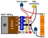
The way I wired my mod without a master on/off switch was one leg of the switch you're using goes to pin 1 (Vin) of the LDO and the other leg of the switch goes to the Batt + contact. And make sure you have an NO switch, not an NC switch.
If you do not want to use the N/C fire switch on pin 2, and you still want want a safety switch, you can add a slider switch (or use the built in box slider switch) to the battery like below.
I just made one like this using the switch that came with the box. I know that the built in box switch it not a high quality switch.
My thoughts about using the built in switch are this....
1. You will only use the switch at the beginning and end of a vap session, so the switch will not get as much use as the fire switch.
2. You will only slide the switch when there is no load on it. With the fire switch still open the current going through the safety switch will be very low and no arcing will happen.
3. The only time this switch will see high current is when it is already close and you hit the fire switch. This should help to reduce the wear on the contacts.
4. I might be totally wrong about this, but I am going to use it this way for a bit and see what happens.
Stoned... the wiring is different for the fire switch if you're not using a master on/off switch.
The way I wired my mod without a master on/off switch was one leg of the switch you're using goes to pin 1 (Vin) of the LDO and the other leg of the switch goes to the Batt + contact. And make sure you have an NO switch, not an NC switch.

Good stuff here, I'm 1.5 years behind on this, building it only now.
Few questions:
If using 3A switch can I avoid 10uF caps?
Or these 10uF caps are used to control\smooth out the current so the 200k POT will not get damaged?
If 10uF Caps are used for a tiny .5A switch then using my 3A switch I should be able to avoid the Caps, correct?
Just want to keep this as simple as possible.
Thank you in advance!
And I would add that although the mosfet relieves the heavy amp load, it's no excuse to use a 50¢ switch, which is mechanically inferior and is not meant for the kind of constant pressing we tend to do.A mosfet is used in line with a 0.5A switch to take the load off the switch. A 3A switch can easily handle the atty load, but not a 0.5A switch. So a mosfet is usually required when using lower amp switches unless you want to repeatedly replace the switch when it fails.
Operations at Rated Load
150 mA 1,000,000


...But after a few puffs it seems like the UCC283T-ADJ is overheating very fast, just killed two of them.
SO maybe I should use the 10uFcaps anyway?

 which I will cut into a smaller size and try to attach.
YW Vadim. Good luck!


A similar, though overpriced, one can be found at RS.I don't think those small caps will help much with drawing the heat away from the regulator. Did you attach a heat sink to the regulator?
I use this one that I buy at digikey: HEAT SINK TO-220 .250" COMPACT