
Build a small 5v box mod with micro-switch.
Hopefully this will help a few people wanting to build these.
A few things worth pointing out before starting. I recommend you build at least 1 regular nicostick, or other mod before starting this. Consider it practice. Its not absolutely necessary, but the experience you get, will help tremendously. When soldering to the pc board, (referred to as pcb from now on), be careful to not use to much solder. You dont want wires shorting out. And before soldering something, double check that its correct.
Read through the whole thing before starting, and if you cant figure something out, sometimes looking at a picture of the finished box will help. Or sometimes just looking a few pictures ahead will help. If really stuck, just post your question. Try not to get frustrated. Each paragraph refers to the picture below it. This may seem longer then some tutorials, because I tried to be as thorough as possible.
Have fun.
Lets start with this.
Its the circuit which will be used. Ive numbered the pins. Thanks to Mark from madvapes for making it available to all of us.

All parts are also from Madvapes, except the battery connector, (I use a J118 connector).
1 3x triple A battery box
1 5v regulator w/control pin
1 micro switch (he has several to choose from)
1 470 ohm resistor
1 - pc board (easy to cut to size)
1 battery connector (not in picture)
Pic 1

The box looks like this to start out.
Pic 2

First, carefully break/pry off the plastic piece covering the switch.Try not to break it but......
Pic 3

Dont worry if a piece breaks off (like it did here), or even if one of the plastic arms that the switch slides onto break off (which also happened, as youll see in later pics).
Pic 4

The switch can come out now, but save the piece you just pulled out to free up the switch, (lying on the left side of box). Youll need it later to hold the switch in place again.
If you broke that piece badly trying to remove it, keep smiling and dont worry. Its not a problem, and will also be addressed later.
Pic 5

The switch will easily come out now by gently prying up the negative battery connection (which is attached to the switch), and also pushing on the switch directly. Free up the black wire so it can be pulled through the hole as you remove the switch.
Pic 6

Ok, the switch is out. And although in this picture the battery contacts are still in, go ahead and take them out also. When you take out the positive contact with the red wire already attached, set that one aside, youre going to use it in a few minutes. After all the contacts are removed, the box will be ready for some grinding, which youll get to soon enough.
[ But before that, heres a few things I recommend to prevent problems. Although they arent absolutely necessary, I have found they make things easier later on. First, use your soldering iron and remove the black wire that comes soldered to the switch, and replace it with a slightly thicker gauge wire, about 2 inches long. When done with that, put it to the side.
Next, take the red wire with the battery contact attached, (the one you set to the side before). Using your soldering iron again, remove the wire from it. Cut off the used part of wire that you just unsoldered. Re-strip, and tin the wire. Now take the bare positive contact to anyplace with a cement floor. Place the contact on the cement floor, with the bump that makes contact with the battery, facing up. Hit it a few times with a hammer to flatten it JUST a few millimeters. Dont hit it too hard. You still want a little bump there, so it can contact the battery. (SEE the connector in PIC 15 for how it should look after it is slightly flattened.) Once thats finished, reattach the red wire securely to the back of the flattened contact, using fresh solder.
The reason for replacing the ground wire, is because the switch assembly may be repeatedly inserted and removed from the box during assembly, and the original wiring can weaken or break off very easily at the solder junction, even if only moved around a minimal amount. The reason for flattening the battery contact is to give the protected batteries a few extra millimeters of room since they are a bit oversize.] Ok, recommendations done.
Pic 7

Although the regulator, switch, and battery contact are already attached here, you can still see the pcb has been cut down from the rough size it was in Pic 1. Its now 5 holes long by 4 holes wide. You can actually cut it to 4 holes by 4 holes if you really want to. When done cutting the pcb to the correct size, insert the regulator into it, and bend the legs 90 degrees. Then cut the legs (evenly) leaving enough to poke through the board and still be soldered, (about 4-5mm past the bend). Now, solder the regulator to the pcb. Then place the regulator w/pcb attached, along with the switch, and the flattened battery contact w/wire attached, in their proper places in the box. Then you can determine the exact length each of those wires needs to be, to connect to the pcb. So measure twice, cut once, and dont cut them to short. Remember to account for the length that will be inserted into the pcb, and then add a few millimeters just to be safe. I removed all the parts from the box only AFTER the wires were cut to the proper length. Once youre done cutting them, and the parts are out of the box again, carefully strip the ends of the wires you cut. Then, tin the wires, and attach them to the pcb.
If you look closely at the picture, you can see the wire from the main switch is attached to the row on the pcb, which corresponds to ground on the regulator (pin 3).
The positive battery contact gets soldered to the row which corresponds to the regulator input (pin 1). It should look exactly like the picture when youre done. Well call it the switch assembly.
You can also see the J118 battery connector has been wired up, and is ready to go. The ground wire is soldered to the inside of the connector, and I suggest you do it that way also. Then you dont have to do any soldering on it, once its in place.
*(If at any time, you are the slightest bit unsure of the pin numbers, refer to Pic 21 to see a numbered regulator)
Pic 8

I combined a few basic steps for this picture.
First, holes were drilled for the battery connector, and also the tact switch Im using. Next, the plastic battery tabs were CAREFULLY ground off with a dremel, and after that, wires are soldered onto the switch, and it is mounted in place with 5 minute epoxy.
After drilling the hole for the battery connector, but BEFORE drilling the hole for the momentary switch, place the switch assembly w/regulator into the box. Temporarily, put your battery connector (that the atty screws onto) completely into the mounting hole for it, ( but dont glue it yet). Now you can see exactly how much room you have for the switch. Mark the spot to drill your hole. Try to keep it closer to the regulator. After you mark it, drill it out.
Because these switches are so small and hard to handle, I find it easier to epoxy the switch when the box is empty, and then just work around it. You also need to be extra careful with the epoxy, making sure that none gets on the switch itself, and prevents it from working. For these tiny tact switches, I put a little bit of epoxy on each corner, and carefully set the switch in place. Hold it there for about 6 minutes, until the epoxy sets a bit. Then using something like a screwdriver, or your finger, to press firmly on the back of the switch, (to hold it in place), and then press the button to make sure it clicks. If it appears stuck, press a little harder. Since you are holding it firmly in place from the back, it shouldnt move. Usually, if theres a tiny bit of epoxy holding the mechanism, one good push will break it free, and after that it will be fine. (But if it did get gunked up with epoxy, and you cant get it working, NOW is the time to find out, since you can still pry it off to replace it.)
Assuming the switch is ok, let the epoxy set for 10 more minutes or so. After that mix up another small batch of epoxy, and carefully apply it around all 4 sides of the switch, to really secure it, and also prevent juice from getting under it. Let the epoxy set.
*Also, look at the bottom right corner of the box, and youll notice one of the plastic support arms that the main switch slides onto, is broken off, (the black wire is pointing to it). I mentioned this earlier, and we will take care of it later.
Pic 9

Take the battery contact as shown in this picture, (make sure spring is on the same side as in the picture).
Pic 10

Use tin snips to cut the battery contact in half. You will be soldering a short jumper wire between those pieces. But first use the floor and hammer trick to flatten the positive contact a little bit, just like you did earlier, with the other positive contact.
Pic 11

I made a simple jig by drilling a hole into a piece of 2x4, to make soldering the jumper wire easier.
Pic 12

Here is the spring, inserted into the jig and ready to be soldered to the other half. The length of wire you see is about 18mm. The insulated part of the wire is about 13mm. Also, if you look closely at the 2 battery contact halves, you can notice I slightly bent the bottom of each one where the wire will be attached. You dont have to bend them at all, but it helps them mount flush to the box.
Pic 13

Battery contacts soldered to jumper.
Pic 14

If the wire was the correct length, the contacts should touch the sides of the box. You also need to make sure that neither contact comes to close to the hole for the battery connector. That could cause a short. You can see in the picture, the contact on the right is too close for comfort, and had to be trimmed a little bit.
Pic 15

Get ready to glue the battery contacts in place. But first insert the switch assembly into the box.
Pic 16

Make sure the switch assembly is pushed completely down, by pressing down on the negative contact at the same time you push down on the switch. And also make sure the negative contact is properly in its slot. Then make sure the positive contact is situated properly, and also touching the bottom of the case. With the switch assembly temporarily in place you can now use batteries to secure the battery contacts while the epoxy sets. So apply a film of epoxy to the back of the contacts and carefully put them in place.
Pic 17

Make sure the contacts being epoxied are in the correct position, then insert the batteries, and since nothing is secure yet, be careful. Put the batteries in spring side first. Once theyre completely in, and holding the epoxied parts, you should eyeball everything to be sure it is exactly where its supposed to be. Let the epoxy set.
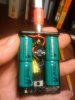
Pic 18

After the epoxy sets, remove the batteries and the switch assembly. Carefully push down the jumper wire so its on the bottom of the box like in the picture. You want it completely out of the way of the hole.
Pic 19

While the epoxy sets on the battery contacts, you can solder the resistor into place. Pictures 20 & 21 each show different angles, so you can get the best view. I stripped about ½ inch from a small piece of black wire, and then cut that insulation to proper length to fit over the exposed leg of the resistor. The resistor gets one leg soldered to the control pin, which is row 4, and the other leg is soldered to ground, which is row 3 of the pcb. Make sure you are keeping the correct orientation of the pins, (1,2,3,4), and not reversing them. (Each pin corresponds to the same row, ie, pin 1 is row 1, pin 2 is row 2, etc I numbered the pins in Pic 21 to help prevent mistakes. So be aware of the pin orientation.
Pic 20

Pic 21

Ok, just a little bit more to do. Time to attach the battery connector that your atty will screw on to. It should already be wired up and ready to go. The wires will be cut to the correct length soon, but first it needs to be epoxied in place. Now is the time to make sure the hole has no burrs, and the connector fits correctly. I recommend screwing a dead atty tightly to the connector before even mixing any epoxy. It will give you a better grip, which makes it easier to properly position the connector.
Before inserting the connector into the hole, smear a thin bead of epoxy around the circumference of the connector, about midway up. (Where the arrow is in the pic)
Pic 22

If possible, you want the red wire towards the bottom of the picture, and the black wire towards the top. Once the connector is fully inserted, use a toothpick and carefully put more epoxy around it as best you can. That will effectively lock it down, and prevent it from slipping and turning freely when you screw on an atty. As soon as you finish applying the epoxy. stand the box up and eyeball the atty to make sure it is straight, and not tilted to one side, or tilted front to back. Hold it straight for 5 more minutes, then let it set for another 15. As the epoxy sets, get ready for the final four connections. Pay very close attention to the wires right now. Look at the picture. There is a red wire, and a black wire coming from the atty. And there is a red wire, and a black wire coming from the tact switch. Those all need to be cut to length before anything else. Youll be soldering those wires into the pcb holes which are closest to the regulator as youll see in the next picture. So put the switch assembly back into the box just like it was in Pic 17, and then stretch the wires out across the pcb. You need to check the length and then carefully cut each wire, so after stripping it, its long enough to be soldered to the pcb.
The black wire from the tact switch will get soldered into row 4 (control).
The black ground wire from the atty will get soldered to row 3 (ground).
The red wire from the atty will get soldered to row 2. (5v output).
The red wire from the tact switch will get soldered to row 1. (input).
All four wires after cutting should reach past where the regulator was soldered to the pcb, and a little past the second set of holes, which is where theyll be soldered. They should be long enough to feed the lead of each wire through the 2nd set of holes on the pcb, and then be soldered. I know I am being redundant about explaining this, but too much has been done to screw it up now.
So, as said earlier, measure twice, cut once. After cutting the wires to the correct length, strip and tin them.
Pic 23

Alright, Im going to be redundant again. Look very closely at this picture, which has the first 3 wires already attached and soldered. Also, look at the next picture that shows all 4 wires soldered. Now get ready to solder.
Heres where each wire goes.
The black wire from the tact switch will get soldered into row 4 (control).
The black ground wire from the atty will get soldered to row 3 (ground).
The red wire from the atty will get soldered to row 2. (5v output).
The red wire from the tact switch will get soldered to row 1. (input).
Pic 24

Heres all 4 wires soldered in place.
Pic 25

Heres a different angle showing the back of the completed pcb. Now tuck the regulator underneath the wires so it looks like the next picture.
Pic 26

When you tuck the regulator under the wires, the switch, and the negative contact attached to it both flip into place. This time they will stay there, so make sure they are both pushed all the way down. Also make sure the positive contact, (in the bottom right corner), is properly in place, and also pushed all the way down.
Now, remember when you started, and pried the cover off the switch, and I said, if that part breaks, or the plastic arms used to hold the switch in place break, I told you, dont worry about it. Well, for anyone who didnt break it, now it the time to put it back. So put a few drops of crazy glue (or epoxy) into those sleeves, and slide them back over the plastic arms that the switch slides down. Hold firmly until it sets. That locks the switch and negative contact in place. However, if yours broke like this one did now well fix it. On this particular box, the plastic arm in the corner broke while removing the switch. So I broke one of the plastic sleeves off the switch cover that was pried off, and filed the broken edge smooth. Thats it in the red box at the top of the picture. A few drops of crazy glue and then slide the single sleeve over the remaining plastic arm, Push it down and hold a few minutes until it sets. The corner with the broken piece simply gets some epoxy, carefully applied with a toothpick, but essentially globbed in the corner, to hold down that side of the switch.. But you need to be very careful the epoxy doesnt seep into the switch before it sets. To prevent that, just tilt the box on its side so gravity keeps the epoxy from seeping towards the switch. If both of the plastic arms broke, you can actually use epoxy on both sides to hold it securely in place. Just do one side at a time, letting it set before doing the other side, and be careful you dont let epoxy seep into the switch. All thats left now is to secure the last battery contact (in the bottom right corner).
Pic 27

In the top right corner, you can see the epoxy used to secure that side of the switch, and you can also see the single plastic sleeve, securing the other side. Ok, done with the switch.
To keep the last battery contact in place, I recommend a hot glue gun. But before gluing it in place, insert the batteries to keep pressure on it. Fill that corner with hot glue, and make sure to get some glue behind BOTH tabs supporting the battery contact, because they take a lot of force when the batteries are in place, and the glue adds lots of strength.
If you dont have a glue gun, you can also use epoxy, just be sure it doesnt seep into the switch. THATS IT, YOU ARE DONE! You can vape on it right now with the cover off, but let the glue and epoxy fully cure for at least a few hours before vaping with the box closed.
Pic 28

Completed 5 volt - 3x triple A box mod.


Congratulations, and enjoy 5 volt vaping. I hope you liked this tutorial.
Hopefully this will help a few people wanting to build these.
A few things worth pointing out before starting. I recommend you build at least 1 regular nicostick, or other mod before starting this. Consider it practice. Its not absolutely necessary, but the experience you get, will help tremendously. When soldering to the pc board, (referred to as pcb from now on), be careful to not use to much solder. You dont want wires shorting out. And before soldering something, double check that its correct.
Read through the whole thing before starting, and if you cant figure something out, sometimes looking at a picture of the finished box will help. Or sometimes just looking a few pictures ahead will help. If really stuck, just post your question. Try not to get frustrated. Each paragraph refers to the picture below it. This may seem longer then some tutorials, because I tried to be as thorough as possible.
Have fun.
Lets start with this.
Its the circuit which will be used. Ive numbered the pins. Thanks to Mark from madvapes for making it available to all of us.

All parts are also from Madvapes, except the battery connector, (I use a J118 connector).
1 3x triple A battery box
1 5v regulator w/control pin
1 micro switch (he has several to choose from)
1 470 ohm resistor
1 - pc board (easy to cut to size)
1 battery connector (not in picture)
Pic 1

The box looks like this to start out.
Pic 2

First, carefully break/pry off the plastic piece covering the switch.Try not to break it but......
Pic 3

Dont worry if a piece breaks off (like it did here), or even if one of the plastic arms that the switch slides onto break off (which also happened, as youll see in later pics).
Pic 4

The switch can come out now, but save the piece you just pulled out to free up the switch, (lying on the left side of box). Youll need it later to hold the switch in place again.
If you broke that piece badly trying to remove it, keep smiling and dont worry. Its not a problem, and will also be addressed later.
Pic 5

The switch will easily come out now by gently prying up the negative battery connection (which is attached to the switch), and also pushing on the switch directly. Free up the black wire so it can be pulled through the hole as you remove the switch.
Pic 6

Ok, the switch is out. And although in this picture the battery contacts are still in, go ahead and take them out also. When you take out the positive contact with the red wire already attached, set that one aside, youre going to use it in a few minutes. After all the contacts are removed, the box will be ready for some grinding, which youll get to soon enough.
[ But before that, heres a few things I recommend to prevent problems. Although they arent absolutely necessary, I have found they make things easier later on. First, use your soldering iron and remove the black wire that comes soldered to the switch, and replace it with a slightly thicker gauge wire, about 2 inches long. When done with that, put it to the side.
Next, take the red wire with the battery contact attached, (the one you set to the side before). Using your soldering iron again, remove the wire from it. Cut off the used part of wire that you just unsoldered. Re-strip, and tin the wire. Now take the bare positive contact to anyplace with a cement floor. Place the contact on the cement floor, with the bump that makes contact with the battery, facing up. Hit it a few times with a hammer to flatten it JUST a few millimeters. Dont hit it too hard. You still want a little bump there, so it can contact the battery. (SEE the connector in PIC 15 for how it should look after it is slightly flattened.) Once thats finished, reattach the red wire securely to the back of the flattened contact, using fresh solder.
The reason for replacing the ground wire, is because the switch assembly may be repeatedly inserted and removed from the box during assembly, and the original wiring can weaken or break off very easily at the solder junction, even if only moved around a minimal amount. The reason for flattening the battery contact is to give the protected batteries a few extra millimeters of room since they are a bit oversize.] Ok, recommendations done.
Pic 7

Although the regulator, switch, and battery contact are already attached here, you can still see the pcb has been cut down from the rough size it was in Pic 1. Its now 5 holes long by 4 holes wide. You can actually cut it to 4 holes by 4 holes if you really want to. When done cutting the pcb to the correct size, insert the regulator into it, and bend the legs 90 degrees. Then cut the legs (evenly) leaving enough to poke through the board and still be soldered, (about 4-5mm past the bend). Now, solder the regulator to the pcb. Then place the regulator w/pcb attached, along with the switch, and the flattened battery contact w/wire attached, in their proper places in the box. Then you can determine the exact length each of those wires needs to be, to connect to the pcb. So measure twice, cut once, and dont cut them to short. Remember to account for the length that will be inserted into the pcb, and then add a few millimeters just to be safe. I removed all the parts from the box only AFTER the wires were cut to the proper length. Once youre done cutting them, and the parts are out of the box again, carefully strip the ends of the wires you cut. Then, tin the wires, and attach them to the pcb.
If you look closely at the picture, you can see the wire from the main switch is attached to the row on the pcb, which corresponds to ground on the regulator (pin 3).
The positive battery contact gets soldered to the row which corresponds to the regulator input (pin 1). It should look exactly like the picture when youre done. Well call it the switch assembly.
You can also see the J118 battery connector has been wired up, and is ready to go. The ground wire is soldered to the inside of the connector, and I suggest you do it that way also. Then you dont have to do any soldering on it, once its in place.
*(If at any time, you are the slightest bit unsure of the pin numbers, refer to Pic 21 to see a numbered regulator)
Pic 8

I combined a few basic steps for this picture.
First, holes were drilled for the battery connector, and also the tact switch Im using. Next, the plastic battery tabs were CAREFULLY ground off with a dremel, and after that, wires are soldered onto the switch, and it is mounted in place with 5 minute epoxy.
After drilling the hole for the battery connector, but BEFORE drilling the hole for the momentary switch, place the switch assembly w/regulator into the box. Temporarily, put your battery connector (that the atty screws onto) completely into the mounting hole for it, ( but dont glue it yet). Now you can see exactly how much room you have for the switch. Mark the spot to drill your hole. Try to keep it closer to the regulator. After you mark it, drill it out.
Because these switches are so small and hard to handle, I find it easier to epoxy the switch when the box is empty, and then just work around it. You also need to be extra careful with the epoxy, making sure that none gets on the switch itself, and prevents it from working. For these tiny tact switches, I put a little bit of epoxy on each corner, and carefully set the switch in place. Hold it there for about 6 minutes, until the epoxy sets a bit. Then using something like a screwdriver, or your finger, to press firmly on the back of the switch, (to hold it in place), and then press the button to make sure it clicks. If it appears stuck, press a little harder. Since you are holding it firmly in place from the back, it shouldnt move. Usually, if theres a tiny bit of epoxy holding the mechanism, one good push will break it free, and after that it will be fine. (But if it did get gunked up with epoxy, and you cant get it working, NOW is the time to find out, since you can still pry it off to replace it.)
Assuming the switch is ok, let the epoxy set for 10 more minutes or so. After that mix up another small batch of epoxy, and carefully apply it around all 4 sides of the switch, to really secure it, and also prevent juice from getting under it. Let the epoxy set.
*Also, look at the bottom right corner of the box, and youll notice one of the plastic support arms that the main switch slides onto, is broken off, (the black wire is pointing to it). I mentioned this earlier, and we will take care of it later.
Pic 9

Take the battery contact as shown in this picture, (make sure spring is on the same side as in the picture).
Pic 10

Use tin snips to cut the battery contact in half. You will be soldering a short jumper wire between those pieces. But first use the floor and hammer trick to flatten the positive contact a little bit, just like you did earlier, with the other positive contact.
Pic 11

I made a simple jig by drilling a hole into a piece of 2x4, to make soldering the jumper wire easier.
Pic 12

Here is the spring, inserted into the jig and ready to be soldered to the other half. The length of wire you see is about 18mm. The insulated part of the wire is about 13mm. Also, if you look closely at the 2 battery contact halves, you can notice I slightly bent the bottom of each one where the wire will be attached. You dont have to bend them at all, but it helps them mount flush to the box.
Pic 13

Battery contacts soldered to jumper.
Pic 14

If the wire was the correct length, the contacts should touch the sides of the box. You also need to make sure that neither contact comes to close to the hole for the battery connector. That could cause a short. You can see in the picture, the contact on the right is too close for comfort, and had to be trimmed a little bit.
Pic 15

Get ready to glue the battery contacts in place. But first insert the switch assembly into the box.
Pic 16

Make sure the switch assembly is pushed completely down, by pressing down on the negative contact at the same time you push down on the switch. And also make sure the negative contact is properly in its slot. Then make sure the positive contact is situated properly, and also touching the bottom of the case. With the switch assembly temporarily in place you can now use batteries to secure the battery contacts while the epoxy sets. So apply a film of epoxy to the back of the contacts and carefully put them in place.
Pic 17

Make sure the contacts being epoxied are in the correct position, then insert the batteries, and since nothing is secure yet, be careful. Put the batteries in spring side first. Once theyre completely in, and holding the epoxied parts, you should eyeball everything to be sure it is exactly where its supposed to be. Let the epoxy set.
Pic 18

After the epoxy sets, remove the batteries and the switch assembly. Carefully push down the jumper wire so its on the bottom of the box like in the picture. You want it completely out of the way of the hole.
Pic 19

While the epoxy sets on the battery contacts, you can solder the resistor into place. Pictures 20 & 21 each show different angles, so you can get the best view. I stripped about ½ inch from a small piece of black wire, and then cut that insulation to proper length to fit over the exposed leg of the resistor. The resistor gets one leg soldered to the control pin, which is row 4, and the other leg is soldered to ground, which is row 3 of the pcb. Make sure you are keeping the correct orientation of the pins, (1,2,3,4), and not reversing them. (Each pin corresponds to the same row, ie, pin 1 is row 1, pin 2 is row 2, etc I numbered the pins in Pic 21 to help prevent mistakes. So be aware of the pin orientation.
Pic 20

Pic 21

Ok, just a little bit more to do. Time to attach the battery connector that your atty will screw on to. It should already be wired up and ready to go. The wires will be cut to the correct length soon, but first it needs to be epoxied in place. Now is the time to make sure the hole has no burrs, and the connector fits correctly. I recommend screwing a dead atty tightly to the connector before even mixing any epoxy. It will give you a better grip, which makes it easier to properly position the connector.
Before inserting the connector into the hole, smear a thin bead of epoxy around the circumference of the connector, about midway up. (Where the arrow is in the pic)
Pic 22

If possible, you want the red wire towards the bottom of the picture, and the black wire towards the top. Once the connector is fully inserted, use a toothpick and carefully put more epoxy around it as best you can. That will effectively lock it down, and prevent it from slipping and turning freely when you screw on an atty. As soon as you finish applying the epoxy. stand the box up and eyeball the atty to make sure it is straight, and not tilted to one side, or tilted front to back. Hold it straight for 5 more minutes, then let it set for another 15. As the epoxy sets, get ready for the final four connections. Pay very close attention to the wires right now. Look at the picture. There is a red wire, and a black wire coming from the atty. And there is a red wire, and a black wire coming from the tact switch. Those all need to be cut to length before anything else. Youll be soldering those wires into the pcb holes which are closest to the regulator as youll see in the next picture. So put the switch assembly back into the box just like it was in Pic 17, and then stretch the wires out across the pcb. You need to check the length and then carefully cut each wire, so after stripping it, its long enough to be soldered to the pcb.
The black wire from the tact switch will get soldered into row 4 (control).
The black ground wire from the atty will get soldered to row 3 (ground).
The red wire from the atty will get soldered to row 2. (5v output).
The red wire from the tact switch will get soldered to row 1. (input).
All four wires after cutting should reach past where the regulator was soldered to the pcb, and a little past the second set of holes, which is where theyll be soldered. They should be long enough to feed the lead of each wire through the 2nd set of holes on the pcb, and then be soldered. I know I am being redundant about explaining this, but too much has been done to screw it up now.
So, as said earlier, measure twice, cut once. After cutting the wires to the correct length, strip and tin them.
Pic 23

Alright, Im going to be redundant again. Look very closely at this picture, which has the first 3 wires already attached and soldered. Also, look at the next picture that shows all 4 wires soldered. Now get ready to solder.
Heres where each wire goes.
The black wire from the tact switch will get soldered into row 4 (control).
The black ground wire from the atty will get soldered to row 3 (ground).
The red wire from the atty will get soldered to row 2. (5v output).
The red wire from the tact switch will get soldered to row 1. (input).
Pic 24

Heres all 4 wires soldered in place.
Pic 25

Heres a different angle showing the back of the completed pcb. Now tuck the regulator underneath the wires so it looks like the next picture.
Pic 26

When you tuck the regulator under the wires, the switch, and the negative contact attached to it both flip into place. This time they will stay there, so make sure they are both pushed all the way down. Also make sure the positive contact, (in the bottom right corner), is properly in place, and also pushed all the way down.
Now, remember when you started, and pried the cover off the switch, and I said, if that part breaks, or the plastic arms used to hold the switch in place break, I told you, dont worry about it. Well, for anyone who didnt break it, now it the time to put it back. So put a few drops of crazy glue (or epoxy) into those sleeves, and slide them back over the plastic arms that the switch slides down. Hold firmly until it sets. That locks the switch and negative contact in place. However, if yours broke like this one did now well fix it. On this particular box, the plastic arm in the corner broke while removing the switch. So I broke one of the plastic sleeves off the switch cover that was pried off, and filed the broken edge smooth. Thats it in the red box at the top of the picture. A few drops of crazy glue and then slide the single sleeve over the remaining plastic arm, Push it down and hold a few minutes until it sets. The corner with the broken piece simply gets some epoxy, carefully applied with a toothpick, but essentially globbed in the corner, to hold down that side of the switch.. But you need to be very careful the epoxy doesnt seep into the switch before it sets. To prevent that, just tilt the box on its side so gravity keeps the epoxy from seeping towards the switch. If both of the plastic arms broke, you can actually use epoxy on both sides to hold it securely in place. Just do one side at a time, letting it set before doing the other side, and be careful you dont let epoxy seep into the switch. All thats left now is to secure the last battery contact (in the bottom right corner).
Pic 27

In the top right corner, you can see the epoxy used to secure that side of the switch, and you can also see the single plastic sleeve, securing the other side. Ok, done with the switch.
To keep the last battery contact in place, I recommend a hot glue gun. But before gluing it in place, insert the batteries to keep pressure on it. Fill that corner with hot glue, and make sure to get some glue behind BOTH tabs supporting the battery contact, because they take a lot of force when the batteries are in place, and the glue adds lots of strength.
If you dont have a glue gun, you can also use epoxy, just be sure it doesnt seep into the switch. THATS IT, YOU ARE DONE! You can vape on it right now with the cover off, but let the glue and epoxy fully cure for at least a few hours before vaping with the box closed.
Pic 28

Completed 5 volt - 3x triple A box mod.


Congratulations, and enjoy 5 volt vaping. I hope you liked this tutorial.
Last edited:


")