Dan,
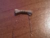
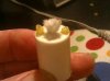
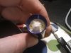
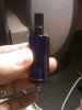
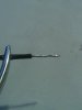
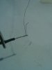
Honestly that looks like a flooder to me. Any excess mist or condensate will collect in the bottom. Your design with the silicone tube with just the tube shorter should cause extra feed. The filler can be positioned so it can't move easily, leaving the center opening clear. The quick change coil can be moved to the position in your original design by just raising/extending the posts. I've used IC socket pins in a couple that worked well. They plug into each other when removed from the socket.
hova,
It could be done, no doubt, its how far can you go? Many want only penstyles and the glass, being dead thermal mass, has to be heated to approx 420-430* to vaporize PG/VG. That kills the use of penstyle batteries and their users. mod uses could do it, but it will still be vaporizing for a bit when its off as the glass has now stored the heat. It wont be an instant draw either.
Most non cigar autos use a microphone as the sensor. It listens for the hiss sound and activates. Note: These do work well at the beach in your swimming trunk pockets! lol This I know for sure! Crashing waves and surf noise...eeeouch!
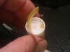
The silicone conical disc usually has holes in the top to allow the his to be heard, air to pass and actually acts as a trap for excess liquid. It is the protector of the mic unit. It too fires off a small FET to handle the current in most cases.
As many dead attys ppl end up with mesh isn't really a problem.
Carbon items just don't seem to fair well in the ecig, so far. Its way to conductive.
Someone mentioned using a graphite core. I measured it and no way that would work.
There is no reason a wick into a "well" shouldn't work. Just the recharge time which depends on a lot of factors, but it would be my 1st attempt with cartos. It should be easy to tune for individual use.
Honestly that looks like a flooder to me. Any excess mist or condensate will collect in the bottom. Your design with the silicone tube with just the tube shorter should cause extra feed. The filler can be positioned so it can't move easily, leaving the center opening clear. The quick change coil can be moved to the position in your original design by just raising/extending the posts. I've used IC socket pins in a couple that worked well. They plug into each other when removed from the socket.
hova,
It could be done, no doubt, its how far can you go? Many want only penstyles and the glass, being dead thermal mass, has to be heated to approx 420-430* to vaporize PG/VG. That kills the use of penstyle batteries and their users. mod uses could do it, but it will still be vaporizing for a bit when its off as the glass has now stored the heat. It wont be an instant draw either.
Most non cigar autos use a microphone as the sensor. It listens for the hiss sound and activates. Note: These do work well at the beach in your swimming trunk pockets! lol This I know for sure! Crashing waves and surf noise...eeeouch!
The silicone conical disc usually has holes in the top to allow the his to be heard, air to pass and actually acts as a trap for excess liquid. It is the protector of the mic unit. It too fires off a small FET to handle the current in most cases.
As many dead attys ppl end up with mesh isn't really a problem.
Carbon items just don't seem to fair well in the ecig, so far. Its way to conductive.
Someone mentioned using a graphite core. I measured it and no way that would work.
There is no reason a wick into a "well" shouldn't work. Just the recharge time which depends on a lot of factors, but it would be my 1st attempt with cartos. It should be easy to tune for individual use.
")