VV Weller BP645

Status
Not open for further replies.

bstedh

Ultra Member
ECF Veteran
Verified Member
Apr 5, 2011
1,551
581
Northern Minnesota
www.clear.com
Still waiting impatiently for USPS... I think the electronics will arrive long before the batteries.

Wow the digi key order is already here.... I didn't realize digi key was located here in MN... Yea!!! Now waiting for my batts from MadVapes.... USPS sucks...
 

bstedh

Ultra Member
ECF Veteran
Verified Member
Apr 5, 2011
1,551
581
Northern Minnesota
www.clear.com
I am currently working out how I want to mount the POT... I don't want to have to open up the body to adjust. I think I will widen out the existing LED window hole and mount it there. I just need to figure out how to secure it as I cant just glob epoxy on the back side because the center shaft goes all the way through and would get glued into one setting. Unfortunately these don't have any mounting strategy other than soldering the 3 leads to a board. I may cut a small piece of board to mount it to just to have something solid for it to sit against. This would also give me something to glob the epoxy onto...

I will take some pictures of where I am at latter today.
 

bstedh

Ultra Member
ECF Veteran
Verified Member
Apr 5, 2011
1,551
581
Northern Minnesota
www.clear.com
Sorry, I got side tracked last night trying to mod some Vortex's and cutting my 24mg juice with VG... I will be home alone this weekend so I will get back to the Weller this weekend and take pics of my progress as I go along. Hopefully my batteries will be in today or tomorrow so I will have more incentive to get moving on this thing. I think I have my strategy figured out. I will have to do some creative epoxy molding to get things the way I want them...
 

bstedh

Ultra Member
ECF Veteran
Verified Member
Apr 5, 2011
1,551
581
Northern Minnesota
www.clear.com
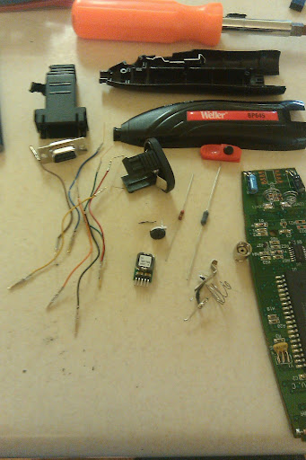
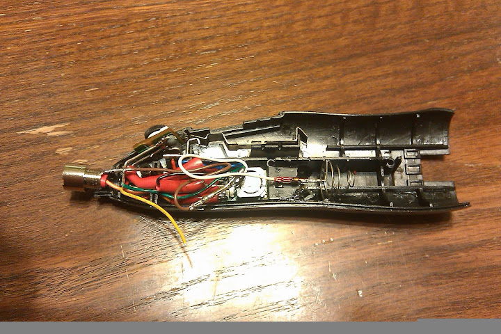
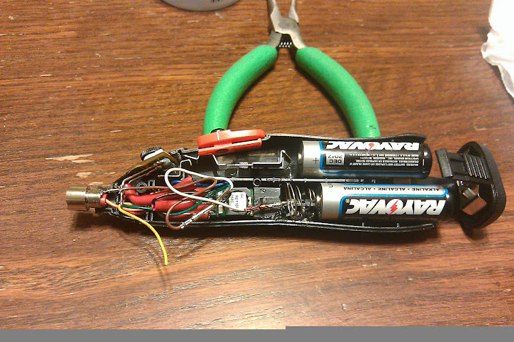
Ok, here are some photos of my progress... My heat shrink tube is way to big... Don't have the batteries yet so I can't test anything before securing it all in place...

IMAG0074.jpg

IMAG0075.jpg

IMAG0076.jpg

IMAG0077.jpg

IMAG0078.jpg

IMAG0079.jpg

IMAG0080.jpg

IMAG0081.jpg

IMAG0082.jpg
 

bstedh

Ultra Member
ECF Veteran
Verified Member
Apr 5, 2011
1,551
581
Northern Minnesota
www.clear.com
All right,,, I finally got it working. I had to re-do the trimmer circuit. I had an intermittent short somewhere and it kept jumping up to almost 7V on me! Talk about a nasty taste...

Everything is pretty much as pictured. I haven't completely secured everything in place yet because I still want to add a couple of led's and some voltage test points. But for right now it is rocking great plumes of vape. It even brought some of my clogged up cartos back to life by burning through the gunked up coils...

I love the factory switch on this thing... Slide it back and it can't be turned on by mistake.

I will be adjusting the position of the POT as I want it recessed a little because it is to easy to turn.
 

bstedh

Ultra Member
ECF Veteran
Verified Member
Apr 5, 2011
1,551
581
Northern Minnesota
www.clear.com
I should have read the spec sheet on the regulator a little closer.. The control pin on this model is open = on, I should have looked for the one the the control pin is open = off. This would allow integration of a tactile switch without a mosfet. The setup I am using doesn't really matter as I am switching the main power but for future mods I am going to look for the other version.
 

MickeyRat

Vaping Master
ECF Veteran
Verified Member
Mar 4, 2011
3,466
1,558
68
Hickory, NC
I should have read the spec sheet on the regulator a little closer.. The control pin on this model is open = on, I should have looked for the one the the control pin is open = off. This would allow integration of a tactile switch without a mosfet. The setup I am using doesn't really matter as I am switching the main power but for future mods I am going to look for the other version.

When you find it, please post the digikey link. I always wind up lost on there. :)
 

WillyB

Vaping Master
ECF Veteran
Oct 21, 2009
3,709
591
USA
I should have read the spec sheet on the regulator a little closer.. The control pin on this model is open = on, I should have looked for the one the the control pin is open = off. This would allow integration of a tactile switch without a mosfet. The setup I am using doesn't really matter as I am switching the main power but for future mods I am going to look for the other version.
Read the data sheet again. It seems you can use some crappy tact switch with this, but note anytime control/enable/inhibit pins are involved you will need to use your master switch to prevent the current leaching they incur. Remember the regulator is now always powered, just not enabled.

The On/Off Control is normally controlled by a switch or open collector or open drain transistor.
But it may also be driven with external logic or by applying appropriate external
voltages
which are referenced to Input Common.
Positive polarity models are enabled when the On/Off pin is left open or is
pulled high to +Vin with respect to –Vin
. Positive-polarity devices are disabled
when the On/Off is grounded
or brought to within a low voltage (see Specifications)
with respect to –Vin.
So basically to turn it off you need to pull the pin the ground, a standard 'pulldown down' resistor approach should do it. Probably any value from 1k to 10k or so should work. The value you choose will also determine how much current the tact will need to handle. Although I have no idea how to figure this as I don't use control pins.

Now how do we turn the reg on? Again from the datasheet.

Remote On/Off Control (Note 5) [Standard version]
Positive Logic ON = +2 V. to +Vin max. or open pin
So basically we just need to hit the pin with more than 2V to enable it.

quiz_2.jpg


Should work. Right? Am I quoting from the model you have?

As far as caps, although I have no hard evidence, it seems that an input cap may in fact help out your batteries and vape times a bit. In this case kind of a little cushion as the PWM circuit pounds away at the battery. :)
 

bstedh

Ultra Member
ECF Veteran
Verified Member
Apr 5, 2011
1,551
581
Northern Minnesota
www.clear.com
I think you sum it up pretty good. My concern initially was how much power would be getting drained when not in use. I will use the control circuit in the future but will add a master power switch. The weller is set up where you don't need the secondary switch as it has a dual action switch so you don't have to worry about it firing in the off position.

With the model regulator I have you would need to use a normally closed switch as it requires a positive voltage to turn it off. This means that there would be an even higher voltage drain when not in use.
 

WillyB

Vaping Master
ECF Veteran
Oct 21, 2009
3,709
591
USA
... With the model regulator I have you would need to use a normally closed switch as it requires a positive voltage to turn it off. This means that there would be an even higher voltage drain when not in use.
I'm confused. Post the exact # of your reg.

I assumed it's this one:

OKR-T/3-W12-C Murata Power Solutions DC/DC Converters & Regulators

If so you could use a more common, readily available, low amp rated N.O. switch wired as per my post.
 
Status
Not open for further replies.

Users who are viewing this thread