Tired of manual switches? Simple Touch switch pass thru for under $15.00

Status
Not open for further replies.

Scubabatdan

Vaping Master
ECF Veteran
Verified Member
Jul 14, 2009
4,749
6,733
60
Dothan, AL
Hey everyone, I was tired of manual switches and constantly replacing them... so I made a nice little USB passthru with a touch switch.

Here is the parts list:
(1) USB Cable (old mouse)
(1) Old 510 atty connector
(1) New 510 battery connector $1.99:
510 Battery Connector, Gold, Large Hole
(1) MOSFET part number IRF8736TRPBFCT-ND 1.28 (AKA IRF8736PbF) $1.28:
Digi-Key - IRF8736TRPBFCT-ND (Manufacturer - IRF8736TRPBF)
(1) 100M SMD resistor $5.27:
Digi-Key - HVCB2512FKC100MCT-ND (Manufacturer - HVCB2512FKC100M)
(1) 47k SMD resistor $1.10:
Digi-Key - 541-47KPACT-ND (Manufacturer - CRCW201047K0JNEFHP)
(1) AAA Battery Box $1.99 :
Enclosed AAA Battery Holder : Battery Holders | RadioShack.com

iPhone 050.jpg
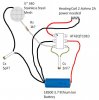
The only trick is the SMD resistors, soldering them is a pain. The MOSFET switch I cut legs 2 and 3 off, only needed 1 and 4 on the left side. Pin 1 is by the dot and is battery in, pin 4 in the picture is in the lower right corner. Legs 1 and 4 you have to straighten and spread out a bit to be able to solder to the 100M resistor. The 47k resistor is solders directly to the 100M resistor and the (-) touch contact is soldered there. Pins 5-8 are for (-) out to the ATTY.

iPhone 051.jpg
I used a 510 atty connector and the touch contact point and it works great. Power in from the USB goes direct to the ATTY center, and then runs onto the center touch point.
iPhone 055.jpg
I drilled out a rough hold an continually checked the hole against the atty connector until I could screw it into the hole.
iPhone 052.jpg
Once I had the height I wanted I screwed it all the way in, put a drop of super glue on the threads and backed it up to the height I wanted. Then I just let it dry. Do this AFTER you have soldered the wires to it. It will melt the plastic otherwise.
iPhone 053.jpg
Last thing was a heat shrink to cover the electronics and a little Quick Steel Plastic Repair around the ATTY connector to help keep it solid.


Here is a quick video showing its operation. It works with completely dry fingers, so no worrying about moisture.

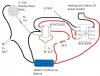
The nice thing is this setup can be incorporated in just about anything, just wire it inline where the (-) goes to the atty connector and run (+) wire from the Atty connector to the (+) touch point.
This MOSFET switch will handle up to 18v at 30A so it can be used in HV PV's.

Hope yall like it...
Dan
 
Last edited:

Scubabatdan

Vaping Master
ECF Veteran
Verified Member
Jul 14, 2009
4,749
6,733
60
Dothan, AL
Nice Dan, very informative.
I've notice ya in to SMD's. Nice, but if you want to knock $3.09 off the price, Digi-key has thick film 100megs for $2.18. I picked up some just this week. And got some carbons 10megs for $0.45

Got a link for those?
Thanks for the input!
Dan
 

slopes

Super Member
ECF Veteran
Jul 19, 2009
616
210
London, UK
Very interesting Dan, thanks. And easy to understand.

I'm still waiting for someone to show how to wire up a simple capacitative touch switch - using the very cheap IC's available. Hopefully an electronics wizard will get around to it before too long.

I think the capacitative type switch will be much better as they don't require a skin-connection to be made between two exposed metal surfaces... it's possible to position the single touch-sensitive element BEHIND a plastic surface (ie, inside a mod box), forming a touch 'zone' on the actual plastic box.
 
Last edited:

Scubabatdan

Vaping Master
ECF Veteran
Verified Member
Jul 14, 2009
4,749
6,733
60
Dothan, AL
Very interesting Dan, thanks. And easy to understand.

I'm still waiting for someone to show how to wire up a simple capacitative touch switch - using the very cheap IC's available. Hopefully an electronics wizard will get around to it before too long.

I think the capacitative type switch will be much better as they don't require a skin-connection to be made between two exposed metal surfaces... it's possible to position the single touch-sensitive element BEHIND a plastic surface (ie, inside a mod box), forming a touch 'zone' on the actual plastic box.

Yeah, your talking about q-touch, I have been reading on that, the IC for it is very cheap, just need a reliable "small" sensor to pick up the fingers field to activate it that is small enough to fit into a box and sensitive enough to read through plastic. I think it was ATMEL corp that I was reading on that has been developing that. It is called "proximity mode"
http://www.mouser.com/atmel_qtouch/
Dan
 
Last edited:

slopes

Super Member
ECF Veteran
Jul 19, 2009
616
210
London, UK
Dan - yes q-touch is one version. I bought a very similar-looking (and functioning) IC a few months ago for next-to-nothing from this firm: HobbyTronics | HobbyTronics Touch Switch IC . It has no manufacturer's name on it, so I'm not sure if it actually is a q-touch, or another brand.

The trouble is, I'm virtually illiterate when it comes to technical electronics diagrams - so the simple wiring diagram they show on their website confuses me (although I've worked out some of the scheme can be disregarded for a single switch input). The type of pictorial diagram Raidy made for his touch switch is much clearer for me.

The website says (and I've read in several other places) that the actual sensor itself can be made from any metal. For example, a half-inch diameter disc of fine steel mesh (like the 'Genesis' uses) can be wired to become the sensor, and then glued flat onto the inside surface of the plastic mod box.
 

Scubabatdan

Vaping Master
ECF Veteran
Verified Member
Jul 14, 2009
4,749
6,733
60
Dothan, AL
Dan - yes q-touch is one version. I bought a very similar-looking (and functioning) IC a few months ago for next-to-nothing from this firm: HobbyTronics | HobbyTronics Touch Switch IC . It has no manufacturer's name on it, so I'm not sure if it actually is a q-touch, or another brand.

The trouble is, I'm virtually illiterate when it comes to technical electronics diagrams - so the simple wiring diagram they show on their website confuses me (although I've worked out some of the scheme can be disregarded for a single switch input). The type of pictorial diagram Raidy made for his touch switch is much clearer for me.

The website says (and I've read in several other places) that the actual sensor itself can be made from any metal. For example, a half-inch diameter disc of fine steel mesh (like the 'Genesis' uses) can be wired to become the sensor, and then glued flat onto the inside surface of the plastic mod box.

Ok here is my schematics on a proximity circuit using the ATMEL AT42QT1010, now this is just a mock up I do not have the chips (yet) and have used the lowest values recommended for highest sensitivity.
Would be interesting to see how this works :)
Any thoughts?
Dan
 

Attachments

  • Proximity Touch Circuit.jpg
    Proximity Touch Circuit.jpg
    43.5 KB · Views: 630

slopes

Super Member
ECF Veteran
Jul 19, 2009
616
210
London, UK
Ok here is my schematics on a proximity circuit using the ATMEL AT42QT1010, now this is just a mock up I do not have the chips (yet) and have used the lowest values recommended for highest sensitivity.
Would be interesting to see how this works :)
Any thoughts?
Dan

A thousand thanks to you Dan! I will get hold of a QT1010 and give this a go if it works. Here's another circuit using a QT113G Build your circuit

EDIT: In the UK, the QT1010 is available from Farnell for 55 pence (about 80 cents)!
ATMEL|AT42QT1010-TSHR|SENSOR, TOUCH, CAP, 1CH, 6SOT | Farnell United Kingdom
 
Last edited:

Scubabatdan

Vaping Master
ECF Veteran
Verified Member
Jul 14, 2009
4,749
6,733
60
Dothan, AL
Glad I could help, the QT1010 is the most sensitive touch chip that ATMEL sells. So if there is an ic that will make a proximity touch switch, that would be the best bet.
Let me know how it goes, and if I get it working before you I will post the Cx, Cs, and Rs values.
But according to ATMELs data sheet those are the lowest values for the capacitors for the highest sensitivity level, the resistor I am guessing at.

Dan
 

Java_Az

Ultra Member
ECF Veteran
Verified Member
Aug 29, 2010
2,071
216
Colorado
"Max continuous pin current, any control or drive pin ±20 mA"

That QT1010 chip is going to fry if you try to use it as a direct switch. The above 20mA is from the data sheet. It would make a great gate driver though just add the mosfet from first post to the circuit. Might want to protect the input from current spikes also , I would would add one of these Digi-Key - BAS7005TC-ND (Manufacturer - BAS7005TC) or you could even use a resistor calculated to keep the input current lower the 20mA but the diode is only 16 cents and a better choice in my opinion.

Edit: Going to need a P channel mosfet with it so the Fet from the first post wont work but this one has similar specs and is a P channel http://search.digikey.com/scripts/DkSearch/dksus.dll?Detail&name=UPA2715GR-E2-A-ND
 
Last edited:

Scubabatdan

Vaping Master
ECF Veteran
Verified Member
Jul 14, 2009
4,749
6,733
60
Dothan, AL
"Max continuous pin current, any control or drive pin ±20 mA"

That QT1010 chip is going to fry if you try to use it as a direct switch. The above 20mA is from the data sheet. It would make a great gate driver though just add the mosfet from first post to the circuit. Might want to protect the input from current spikes also , I would would add one of these Digi-Key - BAS7005TC-ND (Manufacturer - BAS7005TC) or you could even use a resistor calculated to keep the input current lower the 20mA but the diode is only 16 cents and a better choice in my opinion.

Edit: Going to need a P channel mosfet with it so the Fet from the first post wont work but this one has similar specs and is a P channel Digi-Key - UPA2715GR-E2-A-ND (Manufacturer - UPA2715GR-E2-A)

Good catch, completely missed that, so how does this circuit look?
Any changes you would make...

Proximity Touch Circuit v2.jpg

Thanks for the input,
Dan

Added:
Crap just noticed you edited your post while I was posting LOL...
I have used this mosfet switch with a standard 50ma switch on the pos line to the G leg (Gate), with the 4.7M resistor in place it does not get the brunt of the power that typically burns low ma switches out. I think this setup should work.
Thoughts...
Dan
 
Last edited:

Java_Az

Ultra Member
ECF Veteran
Verified Member
Aug 29, 2010
2,071
216
Colorado
I have used this mosfet switch with a standard 50ma switch on the pos line to the G leg (Gate), with the 4.7M resistor in place it does not get the brunt of the power that typically burns low ma switches out. I think this setup should work.
Thoughts...

Keep missing the edits: Might need to drop the diode and just use the resistor since after looking again all the low amp diodes are non stock at digikey. But the diode would have done the same thing as the resistor. Might be better to move the resistor to the input of the QT1010 so it will free up your source pins so you can use them. Also might need a different value resistor you want to limit the input to around 15mA to be safe since the maximum is 20mA
 

Scubabatdan

Vaping Master
ECF Veteran
Verified Member
Jul 14, 2009
4,749
6,733
60
Dothan, AL
Keep missing the edits: Might need to drop the diode and just use the resistor since after looking again all the low amp diodes are non stock at digikey. But the diode would have done the same thing as the resistor. Might be better to move the resistor to the input of the QT1010 so it will free up your source pins so you can use them. Also might need a different value resistor you want to limit the input to around 15mA to be safe since the maximum is 20mA

Ok so if R=(V/I) (30=(3.7/.12) then I would need a 30ohm resistor to get approx 12mA through to the pin 5 of the QT1010 chip.
Look good to you?
Dan
 

Attachments

  • Proximity Touch Circuit v3.jpg
    Proximity Touch Circuit v3.jpg
    42.7 KB · Views: 125

Java_Az

Ultra Member
ECF Veteran
Verified Member
Aug 29, 2010
2,071
216
Colorado
You have it figured for 120mA need to add a zero( 3.7/.012 ) so i get 308 ohms next standard i believe is 330 ohm. But after reading this in the data sheet "The OUT pin is active high and can sink or source up to 2 mA. When a large value of Cs
(>20 nF) is used the OUT current should be limited to <1 mA to prevent gain-shifting sideeffects, which happen when the load current creates voltage drops on the die and bondingwires; these small shifts can materially influence the signal level to cause detection instability"

Not so sure if maybe it should be limited to an even lower current. The chip it self only requires less then 500uA to power itself @ 3volts. Then they say to keep the drive pin under 2mA. So maybe limiting it to around 5 mA or even 4 would be better.
 

Scubabatdan

Vaping Master
ECF Veteran
Verified Member
Jul 14, 2009
4,749
6,733
60
Dothan, AL
You have it figured for 120mA need to add a zero( 3.7/.012 ) so i get 308 ohms next standard i believe is 330 ohm. But after reading this in the data sheet "The OUT pin is active high and can sink or source up to 2 mA. When a large value of Cs
(>20 nF) is used the OUT current should be limited to <1 mA to prevent gain-shifting sideeffects, which happen when the load current creates voltage drops on the die and bondingwires; these small shifts can materially influence the signal level to cause detection instability"

Not so sure if maybe it should be limited to an even lower current. The chip it self only requires less then 500uA to power itself @ 3volts. Then they say to keep the drive pin under 2mA. So maybe limiting it to around 5 mA or even 4 would be better.

Darn zeros! LOL
Hey thanks for the check, so to make it easy a 1k ohm resistor (1000 ohms) would be 3.7mA, I think that would be a good starting point. So the final circuit to try looks like this:
Proximity Touch Circuit v4.jpg
Now lets see if it works!
I think I will pick up some resistors in 100ohm incremets through 1k for the Rs resistor for tuning the sensitivity of the pickup sensor.
Dan
 
Last edited:

Scubabatdan

Vaping Master
ECF Veteran
Verified Member
Jul 14, 2009
4,749
6,733
60
Dothan, AL
Good idea with the resistors. Might have to drop the input resistor down a bit also but i kinda doubt it. Only other thing is the mosfet part number might be confusing to people since if they try this and get that part number it will be a N channel .

Well the N channel should work as it sits, the negitive path is open until the gate gets its 1ma volt in to close the gate, and then the circuit will complete. I have used this same chip so there is constant power to the atty, just the negitive side is open until the gate is closed completing the circuit. It could be changed to a P channel, but then the wiring would have to altered... LOL just going with what I know, which is little in electronics, but I am catiching up :)
The only concern I have is if the output mA from the QT1010 chip will be enough to colapse the gate on the MOSFET chip.
Since 3.7vdc is passing through your skin to the G pin in the standard setup first posted, I do not know how many mA are actually going to the G pin. So I am hoping the QT1010 chip will pass enough. Only one way to find out :) BUILD IT!
Dan
 
Status
Not open for further replies.

Users who are viewing this thread