USB rechargeable Nicostick

Status
Not open for further replies.

caesar

Unregistered Supplier
ECF Veteran
Jun 4, 2009
273
1
Bucharest
theprecious.ro
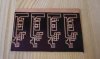
Ladies and gentlemen, here is my Nicostick mod.
Thanks for inspiration goes out to Nicowolf, mogur, kinabaloo and all the fine members of this forum.

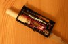
Runs on a Li-Ion 14500 900mAh AA battery, charger is onboard, drawing a maximum of 500mA from the USB port, standard mini-USB connector.

Better watch the movie, it's well explained.

YouTube - DSE901 on USB recharging NicoStick


[Edit:]
Forgot to mention: I am vaping a 24mg Dekang juice cut to 18mg with a 50-50 PG&VG mix. I suspect the MOSFET is helping by flowing more current to the atty. It's way better than a straight button mod.
[end edit]


And here some photos:
 

Attachments

  • PCB.jpg
    PCB.jpg
    20.3 KB · Views: 326
  • DSE801-stick.jpg
    DSE801-stick.jpg
    20 KB · Views: 353
  • nicostick.jpg
    nicostick.jpg
    18.9 KB · Views: 264
Last edited:

stevo_tdo

Super Member
ECF Veteran
May 27, 2009
605
2
Missouri
Looking forward to the microcontroller. Here's my rechargeable nicostick mod from yesterday. I went a little bulkier but with the same charge current. I'm working on getting some custom pcb's made

http://www.tji-java-ide.com/e-cigar...163:i-present-the-amp&catid=42:mods&Itemid=59

or the ecf link to it

http://www.e-cigarette-forum.com/forum/battery-mods/30852-i-present-amp.html


Looks like we were both working on the same idea. Well they say great minds think alike

P.s. I didn't get a chance to watch the vid yet. What charge ic are you using? I'm using a max1811 set to 500ma
 
Last edited:

stevo_tdo

Super Member
ECF Veteran
May 27, 2009
605
2
Missouri
I'm guessing the mcp73831 is the one you like the most?

The whole thing does look very clean. That is what mine is lacking (it has to many wires and connectors). I thought about etching me a board but figured my first one was going to look like crap anyway ( I should of done it though). I'm working on a pcb board now that will hopefully turn out right.

Great system!
 
Last edited:

kinabaloo

Vaping Master
ECF Veteran
Great to see - that's two excellent rechargeable VPs in a week :)

Both not only made, but made to a very high standard.

Caesar - I have posted before, it was quite a while back now, how a heating profile could closely replicate what true temperature control would achieve - i.e. high current initially for a fast heat up and then a lower current for maintaining the heating, without burning (well, lessened likelihood anyway). I guess this is what you have in mind.

I thought Janty were interested in this at one time, but that came to nothing (or at least not with my input). So nice to see someone realise it :)

The promise in this is great - the profile (current versus time) can take into account voltage, atty model, viscosity of the juice (at least if PG, VG, or a mix) etc ...

Quantised into say 8 steps 0.5 seconds apart (much like a graphic equalizer), these profiles could be easily downloaded and shared. Obviously the first 3 would be the key (in fact, maybe sufficient; third level maintained till off time.

I would propse, from the tests I have done: 100% - 70% - 50% as a stater template.

An additional benefit follows - one can achieve big savings in battery power use, meaning considerably extended battery life. Very interesting!
 
Last edited:

DNCMenteer

Senior Member
ECF Veteran
Verified Member
Jul 9, 2009
262
81
Honolulu, HI
Well pick you favorite charge chip. The datasheet will usually list necessary capacitors and resistors. Then beg caesar to show you how to etch a board. I gotta say those boards came out beautifully, i might dare to try myself.


steve, etching aboard is no problemo, i have a electrical shop onboard my ship...US Navy ET here...so putting it together is the easy part....but the location and all parts needed....thats a different story.....but what doyou mean pick my charge chip? what are my choices? where do i look? can YOU teach me? lol any help would be nice...me and another guy on the ship are trying to out do each other....HELP ME WIN... :) thanks
 

caesar

Unregistered Supplier
ECF Veteran
Jun 4, 2009
273
1
Bucharest
theprecious.ro
holy crap that thing is sweet, ive decided to fabricate me a nicostick,...any chance i could get a step by step and parts list for yours? it will be my first but yours is outstanding and i want one....thanks!!

Since you can make your own pcb's it's simple.

Partlist:
1 x mini USB 5pin connector
1 x charger chip, MAX1811 or MAX1555 or MCP73831 and their needed components. Usually 2 x 4,7uF and a few resistors depending on model you choose, get that out of the datasheet.
1 x tiny pushbutton
1 x MOSFET of your liking. go with those that allow 1A@3Vgs and have internal resistance smaller that 0,1 ohm.
I am undecided between RSQ035N03 (40milliohms) and IRF8736 (4milliohms)

The board layout varies depending on charger chip and mosfet.


For now all I can say is that I am very pleased, the battery performs better when charged inside comparing to the charger I ordered with the batteries.

Very Cool, but I would just rather put in another battery and keep vaping while the dead battery charges. I get 8+ hours on a battery[...]

I used to get around 8-9 hours while charging outside, now I'm over the 12h mark with this baby.


Caesar - I have posted before, it was quite a while back now, how a heating profile could closely replicate what true temperature control would achieve - i.e. high current initially for a fast heat up and then a lower current for maintaining the heating, without burning (well, lessened likelihood anyway). I guess this is what you have in mind.

[...]

I would propse, from the tests I have done: 100% - 70% - 50% as a stater template.

An additional benefit follows - one can achieve big savings in battery power use, meaning considerably extended battery life. Very interesting!

Yes, I remember that. Atty and battery life are my concerns too. It will be fully user selectable from the computer so the starter template can be left blank ;)
 

kardjunkie

Senior Member
ECF Veteran
Verified Member
Jul 6, 2009
228
1
Chillicothe, Ohio
I have further developed this project and now I am testing the touch sensor version of the above. Smaller, more efficient and eliminates the need of a button. The only part that was prone to fail.

It seems that it works perfect, if it passes all tests I'll post it here.


Looking forward to it!
 
Status
Not open for further replies.

Users who are viewing this thread