How to wire voltage indicator

Status
Not open for further replies.

Dougiestyle

Vaping Master
ECF Veteran
Verified Member
Feb 5, 2011
3,213
3,957
50
Knoxville, TN USA
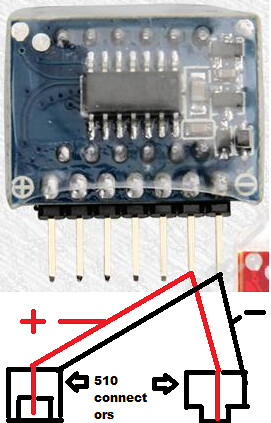
You use the first 2 pins (when looking at the display) on the left. Pin1 is neg. Pin2 is pos. Wire it to the wires leading to your connector. When you have no atty/carto attached you can fire and see your unloaded voltage. Attach a carto/atty and fire. This is your loaded voltage.

A good idea would be to add a clicky on-offf switch or whatever style you choose on either leg of the voltage indicator to turn it off, so your indicator isn't lighing up every time you vape.
 

Madcaprym

Super Member
ECF Veteran
Mar 21, 2011
353
50
Pittsburgh, PA. US
Im also trying to wire this up to make the assembled indicator with the two 510 connectors. More specific, each connector has a pos and neg wire, but where do all 4 wires go on the indicator? Im confused, or do you only use one wire per male and female connector? Can someone describe the correct way to wire a male and female 510 connector to the existing volt indic.? Thank You
 

ChrispyCritter

Ultra Member
ECF Veteran
Jun 4, 2011
1,256
284
55
West of Rochester,N.Y.
Im also trying to wire this up to make the assembled indicator with the two 510 connectors. More specific, each connector has a pos and neg wire, but where do all 4 wires go on the indicator? Im confused, or do you only use one wire per male and female connector? Can someone describe the correct way to wire a male and female 510 connector to the existing volt indic.? Thank You

The simple way would be take 4 wires solder 2 to pin 1 (-) and 2 to pin 2 (+)..solder one of the wires from pin 1 to the ground of one 510 connector and the other to the ground of the other 510 connector. Solder one of the wires from pin 2 to the center post of one 510 connector and the other to the center post on the other 510 connector...

If you already have the wires on the connectors solder the ground wires from the 510 connectors to pin 1 and solder the wires from the center post on the 510 connectors to pin 2.

It might be easier if you twist the wires together from each connector then solder them together then solder the 2 onto the pins. Just remember the ground (-) is pin 1 on the indicator and on the 510 connectors it is the outside of the connector so twist/solder those wires together and then solder to pin 1. The positive (+) is pin 2 on the indicator and the center posts on the 510 connectors..so twist/solder those wires together then onto pin 2.
 
Last edited:

jonuthedevil

Full Member
Verified Member
Nov 24, 2010
44
4
Saudi Arabia
The simple way would be take 4 wires solder 2 to pin 1 (-) and 2 to pin 2 (+)..solder one of the wires from pin 1 to the ground of one 510 connector and the other to the ground of the other 510 connector. Solder one of the wires from pin 2 to the center post of one 510 connector and the other to the center post on the other 510 connector...

If you already have the wires on the connectors solder the ground wires from the 510 connectors to pin 1 and solder the wires from the center post on the 510 connectors to pin 2.

It might be easier if you twist the wires together from each connector then solder them together then solder the 2 onto the pins. Just remember the ground (-) is pin 1 on the indicator and on the 510 connectors it is the outside of the connector so twist/solder those wires together and then solder to pin 1. The positive (+) is pin 2 on the indicator and the center posts on the 510 connectors..so twist/solder those wires together then onto pin 2.


Dear Sir,

I am from saudi arabia & my english is not good..
can you please upload some step by step pictures or diagrams ?
i will be thankful to you

i got these
Lipo Volt Meter

thank you
 

ChrispyCritter

Ultra Member
ECF Veteran
Jun 4, 2011
1,256
284
55
West of Rochester,N.Y.
7202045266_283dd86999.jpg
 
Status
Not open for further replies.

Users who are viewing this thread