Thanks for the input. Not sure if you’ve read the entire thread but I believe I’ll go with the highly experienced and proven works of Mamu and her recommendation on this.
You are using an out of date browser. It may not display this or other websites correctly.
You should upgrade or use an alternative browser.
You should upgrade or use an alternative browser.
Reverse Polarity Protection with the DNA20D
- Thread starter mamu
- Start date
- th_trl_thread_readers 0
- Status
- Not open for further replies.
Correct me if I'm wrong, but I believe you had your diode installed wrong.
http://i.imgur.com/WLaqzLq.png
It's no wonder you were getting a voltage drop... The diode is meant to divert current away from the return path of the pcb input terminals.
edit: and if you're worried about the battery shorting under reverse input conditions, you can put a fuse between the positive terminal of the battery, and the diode. (Or a current-shunt resistor)
The arrangement on the left will block all current flow if the battery is connected incorrectly, when the battery is connected correctly the diode will pass current but will also cause a voltage drop unfortunately, which is why Mamu investigated fets.
The arrangement on the right has a number of issues.
1) The addition of a fuse between the battery and the diode is not optional, it is a must. Without the fuse a reversed battery is effectively short circuited by the diode and given a lithium battery's ability to supply current, something will blow. Worst case, the diode survives, or fails short circuit and the battery goes pop - or BANG. Second scenario the diode fails and the inverted voltage kills the dna board.
2) Even with a fuse in place the diode must be chosen with some care so it can withstand the prodigious current from the lithium battery for as long as it takes for the fuse to blow. This is especially the case when using resettable fuses which are, iirc a little slow to react.
3) The diode voltage drop which caused a problem in the arrangement on the left may also be a cause of trouble in this arrangement. When a battery is connected incorrectly there will be a voltage equal to the diode voltage drop applied to the dna board, equal too but since the battery is upside down this voltage will also be reversed polarity. Now, the -0.2V across a Schottky diode may not be a problem but the -0.7V or more given the potentially high current involved, across a silicon diode may be enough to pop the DNA.
Thanks for the input. Not sure if you’ve read the entire thread but I believe I’ll go with the highly experienced and proven works of Mamu and her recommendation on this.
That's fine. You don't have to listen to me, but at least I know how a diode works.
A diode and a fuse (or resistor) is a lot less expensive than a FET... and you don't even need a shottky diode, a plain diode will work just fine.

something proven --no current drops correctly drawn circuit that ch2468 was on right path just missing a few items..
Simple reverse-polarity-protection circuit has no voltage drop | EDN
Simple reverse-polarity-protection circuit has no voltage drop | EDN
Thanks. I wanted to build dna20 mods with removable batteries so I took notes on what others where doing and added some of my own ideas and had 12 fabbed. They are small .45 x .45. Thinking about using surface mount fuses for the next revision... Thoughts?
Absolutely on the SMT fuses. they are so much smaller.
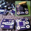
Hey all I have come up with this. It has Reverse polarity protection and fuse. This pic only has one fuse on it but the rest of two.
View attachment 267423
What board maker did you go with? How much were those boards?
JCP! Schweeeeet! Much purrrdier than mine. Nicely done.
TY Mamu! Working on some better artwork for these old eyes. 

What board maker did you go with? How much were those boards?
Osh Park
$5 a square inch but you get 3 copies.
JCP! Schweeeeet! Much purrrdier than mine. Nicely done.
Thanks Littlefeather my first one was not so nice. it was done with a marker, etching solution and dremel.
Absolutely on the SMT fuses. they are so much smaller.
yeah I am researching which ones to go with. not sure about stacking them like you can with these.
yeah I am researching which ones to go with. not sure about stacking them like you can with these.
no need to stack them if you're putting them on a PCB. You can easily draw a couple traces in parallel close by and put the 2 fuses side by side.
This one looks like a good substitute.no need to stack them if you're putting them on a PCB. You can easily draw a couple traces in parallel close by and put the 2 fuses side by side.
Littelfuse 2920L300/15DR
| Part Number | I hold (A) | I trip (A) | V max (Vdc) | I max (A) | Pd typ. (W) | Max Trip Time Current (A) | Max Trip Time (Sec.) | R min (Ω) | R 1max (Ω) |
| 16r300g | 3.0 | 5.1 | 16 | 100 | 2.3 | 15.0 | 1.0 | 0.0380 | 0.0975 |
| 2920l300 | 3.00 | 5.00 | 6 | 40 | 1.50 | 8.00 | 20.00 | 0.015 | 0.048 |
not a perfect match.
- Status
- Not open for further replies.
Similar threads
- Replies
- 1
- Views
- 1K
- Locked
- Replies
- 34
- Views
- 12K
- Replies
- 869
- Views
- 222K
Users who are viewing this thread
Total: 2 (members: 0, guests: 2)


