I think many folks don't fully understand how a protection circuit board works on a Li-ion cell.
Some may have gotten a bad taste in their mouth from the cheap protected cells that they probably overloaded and complained about being crap. There has been little change that I'm aware of in the basic circuit. An integrated circuit that has an overcharge comparator, an under charge comparator, and voltage sensors for overcurrent and short circuit detection, and control signals for the charge/discharge Mosfets. While the part numbers for the components may vary, with some being more reliable than others, the basic parameters are the same.
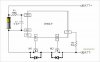
What separates most protected cells is the overcurrent 'trip point'. Cheap cells like the notorious Ultrafire will trip at 2.5 to 3.5 amps by design. Probably because the basic cell couldn't handle more than that. The trip point is a function of the voltage drop under load of the single back-to-back charge/discharge Mosfet. The 'On' resistance of this device is about 40 to 60 milliohms (circuit shown below). This resistance is in addition to the common 'cell internal resistance'. Adding these two resistances together makes the cell seem worse than it really is.
Remember that unprotected cells, whatever the chemistry, do not have this additional resistance. If you've looked at discharge graphs of different cells you will see this as an instantaneous voltage drop at the beginning of the discharge graph. 2 amps through a cell with a single Mosfet chip on the protection board will start off about 0.1 volts lower than an unprotected cell. What goes on later in the graph is a function of the cell itself.
Side note: Most discharge graphs set the horizontal scale for mah and compare the discharge capacity of various cells with a 3100 mah cell looking better than a 2600mah cell. When you set the horizontal scale for zero to 100% or some partial discharge point, you get to see internal cell performance not just mah. All cells start at the same point on the graph, all cells end at the same point. The shape of the curve tells you what is going on inside.
Moving up the line, there are cells that install a pair of these back-to-back Mosfets in 'parallel' to increase current handling and to cut the voltage drop in about half. So now, twice the current is needed to drop enough voltage through the Mosfets to trip the same controller chip. 6 to 7 amps through the parallel Mosfets drops the same voltage as 3 to 3.5 amps through a single Mosfet only because the resistance has been cut to 20 to 30 milliohms. Pretty much the same protection circuit, just an extra spot on the circuit board filled.
If you find a protected 18650 cell than can handle 8 to 9 amps without tripping the protection circuit, you will probably find all three Mosfet spots filled. Hopefully attached to a cell than can handle that kind of current.
The single and double Mosfet protected cells have gotten a bad rap for failing, tripping out, when most likely they were used outside of the intended design current.
For those into DIY modding (oh no, that means using a soldering iron

) there are add on circuit boards for 8 amp continuous drain currents (trip current about 12 amps) for single or parallel 18650 cells and 26650 cells. These use FOUR Mosfets in parallel. These even work well for high current IMR cells to add all the advantages of a protection circuit, with a lot less voltage drop.
Protection circuits don't work for free. They drop voltage, consume energy, and complicate selecting the correct cell for an application. More severe applications, like subohm RBAs, limit cell selection to only those designed to handle the extra current. In the day of the 2.4 ohm, 3.7 volt vaper, just about anything would work.
Have fun, be safe.


")