
I have the same issues with my apollo tank, Didnt see to affect the functionality of it. In Other news my Apollo Battery has died.. kind of. the center pin got pushed down too far so it wont charge not sure if there is a way to pull it back out a bit. Be careful if you have any tanks or devices that the center pin is out to far as it will push this one down.
You are using an out of date browser. It may not display this or other websites correctly.
You should upgrade or use an alternative browser.
You should upgrade or use an alternative browser.
- Status
- Not open for further replies.
Apollo Battery -center pin
You should be able to get a sharp pin/needle and "stick it " in to the side of the pin
& use it to lift the pin up some ...just a hair & rotate a little and pull up the other side ...
IE: @ 1,5 & 9...(on a clock face) ....
the pin is just that a pin w/big head*, floating in a silicone tube so you are just pulling it up.
* that's what they look like to me anyway, I have NOT actually taken one all the way out to see,
But I have adjusted a bunch of them ...
ego,riva,leo,410's,808's seems like they all get pushed down one time or another
or I'm just ROUGH with the Q-tips
I have the same issues with my apollo tank, Didnt see to affect the functionality of it. In Other news my Apollo Battery has died.. kind of. the center pin got pushed down too far so it wont charge not sure if there is a way to pull it back out a bit. Be careful if you have any tanks or devices that the center pin is out to far as it will push this one down.
You should be able to get a sharp pin/needle and "stick it " in to the side of the pin
& use it to lift the pin up some ...just a hair & rotate a little and pull up the other side ...
IE: @ 1,5 & 9...(on a clock face) ....
the pin is just that a pin w/big head*, floating in a silicone tube so you are just pulling it up.
* that's what they look like to me anyway, I have NOT actually taken one all the way out to see,
But I have adjusted a bunch of them ...
ego,riva,leo,410's,808's seems like they all get pushed down one time or another
or I'm just ROUGH with the Q-tips
ZMax Follow Up to my previous Follow UP
I feel like I'm beating this thing to death; but people are still out there buying them so I want to put this information up for all to find.
Like I said in my previous Follow-Up I had set my ZMax to the side uncertain if I should give it away or dissect it. Well the decision was made for me when I picked it up to respond to this post in the New Members Forum.
When I picked it up to see if a drip shield would fit in the well I noticed a rattle inside. Curious, I took off the bottom cap and sitting in it was this little metal ring.

I immediately recognized it as the positive pin that should be attached to the circuit board.

It's hard to make out in the photo but; you can see on the larger board in the middle of the tube there is a little tab jutting out that this ring sits around. There is a semi circle of solder just above where this ring broke off. You can see some discoloration on the ring in the first picture, that is where it was soldered to the board.
The ZMax has been sitting flat without a battery in it since I posted my last follow up. So, I can't imagine what force acted upon the pin to break it off other than a bad solder joint to begin with. The ring is perfectly smooth other than the bit of solder still on it. They could have scored it a little to make a better connection. The AW ICR batteries I initially used were a little tight when screwing on the bottom cap. That may have helped the connection come loose. I stopped using those after about a week though and switched to AW IMRs which fit without undue force and everything was fine until the unit started behaving oddly. If the damage occurred early on due to the tight fit of the first batteries it might explain some of the strangeness that I experienced.
So, Let's take it apart, shall we?
 The top cap is press fit on and was easy enough to take off. I put an old atty on it to help me get a hold of it.
 To get the board to slide up you'll have to break the glue holding the screen cover to the LED display inside. It shouldn't take much to do it. In mine it was already broken. Which is why my screen cover had moved a couple times. For the other end I used a small flat head from a precision screwdriver set. Once the screen cover is out of the way the board will slide out easily. Be careful you don't loose the button because when the board is out there's nothing to hold it in place. I had to chase it under the desk.
 There are two wires going to the head of the unit. White is soldered to the center pin (positive) on the 510 Connection. Black is going to the body of the head. This is the only place that the board makes a ground connection.
[URL=http://s1060.photobucket.com/albums/t460/SolemnPenguin/ZMax%20Testing/?action=view¤t=IMG_1256_zpsf0eef39b.jpg] A Shot of the larger board with the LED display and button.
 The smaller board. Looks like the power regulator circuit
 [/URL]
 Here's a better picture of the support tab and broken solder connection and what it should look like when I solder it back on.
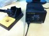
I don't know where my soldering equipment wound up after the last time I moved. So, I'll have to look around my warehouse at work and see if I can find a soldering iron to get the job done. I'll update once I get it working again.
I feel like I'm beating this thing to death; but people are still out there buying them so I want to put this information up for all to find.
Like I said in my previous Follow-Up I had set my ZMax to the side uncertain if I should give it away or dissect it. Well the decision was made for me when I picked it up to respond to this post in the New Members Forum.
When I picked it up to see if a drip shield would fit in the well I noticed a rattle inside. Curious, I took off the bottom cap and sitting in it was this little metal ring.

I immediately recognized it as the positive pin that should be attached to the circuit board.

It's hard to make out in the photo but; you can see on the larger board in the middle of the tube there is a little tab jutting out that this ring sits around. There is a semi circle of solder just above where this ring broke off. You can see some discoloration on the ring in the first picture, that is where it was soldered to the board.
The ZMax has been sitting flat without a battery in it since I posted my last follow up. So, I can't imagine what force acted upon the pin to break it off other than a bad solder joint to begin with. The ring is perfectly smooth other than the bit of solder still on it. They could have scored it a little to make a better connection. The AW ICR batteries I initially used were a little tight when screwing on the bottom cap. That may have helped the connection come loose. I stopped using those after about a week though and switched to AW IMRs which fit without undue force and everything was fine until the unit started behaving oddly. If the damage occurred early on due to the tight fit of the first batteries it might explain some of the strangeness that I experienced.
So, Let's take it apart, shall we?
 The top cap is press fit on and was easy enough to take off. I put an old atty on it to help me get a hold of it.
  To get the board to slide up you'll have to break the glue holding the screen cover to the LED display inside. It shouldn't take much to do it. In mine it was already broken. Which is why my screen cover had moved a couple times. For the other end I used a small flat head from a precision screwdriver set. Once the screen cover is out of the way the board will slide out easily. Be careful you don't loose the button because when the board is out there's nothing to hold it in place. I had to chase it under the desk.
 There are two wires going to the head of the unit. White is soldered to the center pin (positive) on the 510 Connection. Black is going to the body of the head. This is the only place that the board makes a ground connection.
[URL=http://s1060.photobucket.com/albums/t460/SolemnPenguin/ZMax%20Testing/?action=view¤t=IMG_1256_zpsf0eef39b.jpg]
 A Shot of the larger board with the LED display and button.
 The smaller board. Looks like the power regulator circuit
 Here's a better picture of the support tab and broken solder connection and what it should look like when I solder it back on.
I don't know where my soldering equipment wound up after the last time I moved. So, I'll have to look around my warehouse at work and see if I can find a soldering iron to get the job done. I'll update once I get it working again.
Nice pics SP. What a chinsy way to attach that ring.
ZMax Follow Up to my previous Follow UP
I feel like I'm beating this thing to death; but people are still out there buying them so I want to put this information up for all to find.
Like I said in my previous Follow-Up I had set my ZMax to the side uncertain if I should give it away or dissect it. Well the decision was made for me when I picked it up to respond to this post in the New Members Forum.
When I picked it up to see if a drip shield would fit in the well I noticed a rattle inside. Curious, I took off the bottom cap and sitting in it was this little metal ring.
I immediately recognized it as the positive pin that should be attached to the circuit board.
It's hard to make out in the photo but; you can see on the larger board in the middle of the tube there is a little tab jutting out that this ring sits around. There is a semi circle of solder just above where this ring broke off. You can see some discoloration on the ring in the first picture, that is where it was soldered to the board.
The ZMax has been sitting flat without a battery in it since I posted my last follow up. So, I can't imagine what force acted upon the pin to break it off other than a bad solder joint to begin with. The ring is perfectly smooth other than the bit of solder still on it. They could have scored it a little to make a better connection. The AW ICR batteries I initially used were a little tight when screwing on the bottom cap. That may have helped the connection come loose. I stopped using those after about a week though and switched to AW IMRs which fit without undue force and everything was fine until the unit started behaving oddly. If the damage occurred early on due to the tight fit of the first batteries it might explain some of the strangeness that I experienced.
So, Let's take it apart, shall we?
[URL=http://s1060.photobucket.com/albums/t460/SolemnPenguin/ZMax%20Testing/?action=view¤t=IMG_1256_zpsf0eef39b.jpg]
[/URL]
I don't know where my soldering equipment wound up after the last time I moved. So, I'll have to look around my warehouse at work and see if I can find a soldering iron to get the job done. I'll update once I get it working again.


Im glad GV decided to NOT sell this one. Someone is gonna blow their face off with it.
My little $10 lot buy mod is made better than that thing.
You may be right. Like I said I am just guessing and never bought one of these. Good luck on getting it working to your satisfaction.
WallyO I hope you didn't think I was attacking you for your response. If it came across that way I do apologize. I honestly do appreciate the feedback.
Got my new center posts today, going to redo it tomorrow and see if I get the same issues.
Found it!

I scuffed up the ring with some sandpaper and resoldered it. I didn't have any solder on hand so I just melted the big glob that was already there against the ring. Seems firmly attached and the unit is back to it's former self (whatever that was worth). I did just get a perfect sore in the game of "dripping into a moving atty".
I gave it a once over with the microfiber cloth too so it's shiney again. Just for Wally
Attachments
Apollo 6ml tank
.....So after reading all this last night ,
I picked mine up & vaped it for a few hours ....It already had juice in it ...up to the top of window & had had for a week or so.
I checked it (under drip tip & batt connection) often as I used it & I never did see any leaking or puddling ????
I tried all kinds of things, pulling on it hard (draw wise), chain vaping, swinging around as I walked/talked,laying it down .
Not sure why some do leak/puddle & some don't .... hopefully your new heads will be the fix.
I get condensation as well in my ViVi as well as my other tanks, but this is juice, pure juice. The tip comes out soaked at the bottom with juice as well. This happens after one or two draws and by the third you have to stop and clean up the juice from the top and from the 510 connection. The well in the battery is soaked with juice. I get lucky every so often and can get a few more draws before it is gurgling so bad I have to stop and clean it. Condensation would be all over the well, in different areas, not pooling up from one location.
Here is a full size crop of that image.

There is no other liquid or condensation anywhere but where that silicone condom meets the metal air intake post and as I said it was just cleaned prior. I have a replacement stem on the way and I will test it with the new one when it gets here. I just don't think it is simply condensation causing it to flood and leak.
.....So after reading all this last night ,
I picked mine up & vaped it for a few hours ....It already had juice in it ...up to the top of window & had had for a week or so.
I checked it (under drip tip & batt connection) often as I used it & I never did see any leaking or puddling ????
I tried all kinds of things, pulling on it hard (draw wise), chain vaping, swinging around as I walked/talked,laying it down .
Not sure why some do leak/puddle & some don't .... hopefully your new heads will be the fix.
Apollo 6ml tank
.....So after reading all this last night ,
I picked mine up & vaped it for a few hours ....It already had juice in it ...up to the top of window & had had for a week or so.
I checked it (under drip tip & batt connection) often as I used it & I never did see any leaking or puddling ????
I tried all kinds of things, pulling on it hard (draw wise), chain vaping, swinging around as I walked/talked,laying it down .
Not sure why some do leak/puddle & some don't .... hopefully your new heads will be the fix.
Got them today, the old one is getting unusable now. Probably a quality control issue or just a few bad ones in the batch.
Will be trying one tomorrow.
Just got my apollo 10ml and 6ml, My ce9 rebuildable, and Kanger T0 today in the mail. I have a bunch of homework to do tonight so hopefully i can get to these tomorrow.
On opening each one up I did notice on the apollo 10ml the center shaft is press fit into the base crooked. I applied some force and heard a distinct click and now its straight, we'll see if I have any leaking issues when I actually get a chance to mess with it.
The Apollo 6ml looks like its ok, the shaft is straight and the orings look ok.
The CE9 looks pretty nice, not sure how I feel about the cartridge that it uses.
On another note the Kanger T3's are right around the corner. True bottom coil with excellent capacity and work pretty well.
Right around the corner meaning this year? I have noted there is interest in the T3 which has my curiosity piqued.
Right around the corner meaning this year? I have noted there is interest in the T3 which has my curiosity piqued.
More than right around the corner, they're available some places now...
More than right around the corner, they're available some places now...
I found 2 or 3 vendors carrying the T3, all are sold out. This is #2 on my list of things I need to get, #1 is the Ravens.
I found 2 or 3 vendors carrying the T3, all are sold out. This is #2 on my list of things I need to get, #1 is the Ravens.
Just want to let you know that what some vendors were calling a T3 wasn't one. It was the T0
")
Well so far my 6ml apollo is working very well, but based on others' exp this is normal. Will report tomorrow
Last edited:
Well so far my 6ml apollo is working very well, but based on others' exp this is normal. Will report tomorrow
See how it does when you have to do the tank tilt. Only time I have a problem now.
Well first thing out of the box, the positive post is pushed up like the bulli is, difference being i cant get the center post out of this one... So no testing of the CE9 for me as im getting 0.0 ohms on my itaste and gripper...
The 6ml apollo starting spitting at me and is gurgling, something i did? Until this point it worked well, not a ton of vapor but simply ok, same for taste. Im gonna empty it out and take a look, at first glance it looks like the metal sides where the wick slides in are cutting the wick and perhaps allowing liquid in? Ill give it another try but its not looking good so far...
The 6ml apollo starting spitting at me and is gurgling, something i did? Until this point it worked well, not a ton of vapor but simply ok, same for taste. Im gonna empty it out and take a look, at first glance it looks like the metal sides where the wick slides in are cutting the wick and perhaps allowing liquid in? Ill give it another try but its not looking good so far...
- Status
- Not open for further replies.
Similar threads
- Locked
- Replies
- 10
- Views
- 4K
- Locked
- Replies
- 22
- Views
- 2K
- Locked
- Replies
- 39
- Views
- 5K
- Replies
- 94
- Views
- 6K
- Locked
- Replies
- 37
- Views
- 4K
Users who are viewing this thread
Total: 2 (members: 0, guests: 2)